Elements in Harmony IV

36"f/4.5

If it's up there, it's in here.

April, 2006 - May, 2007


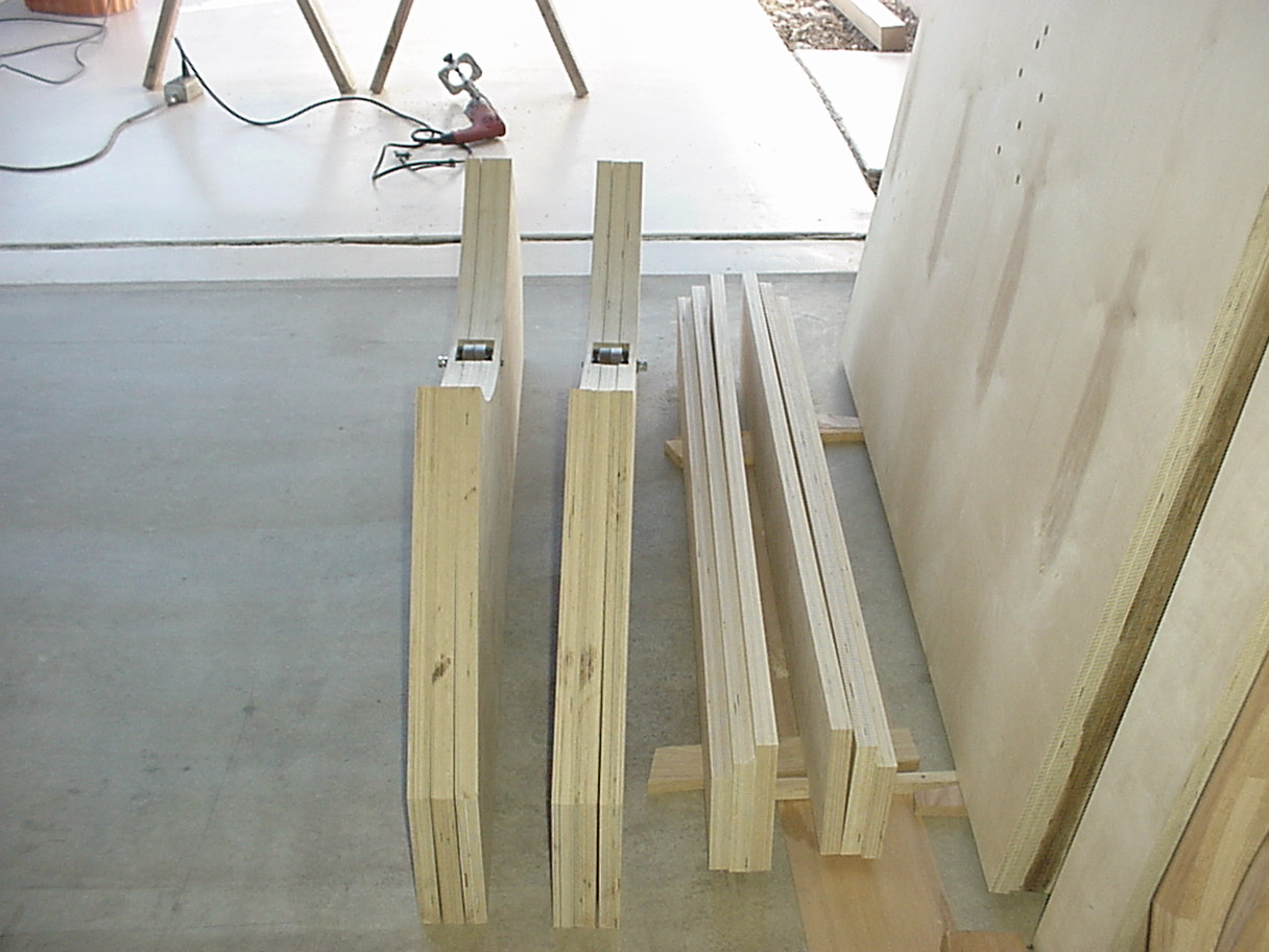
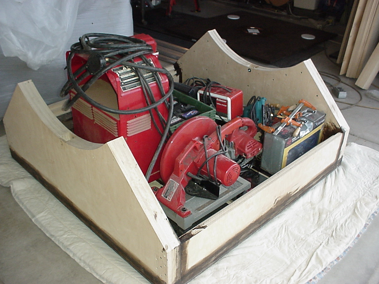
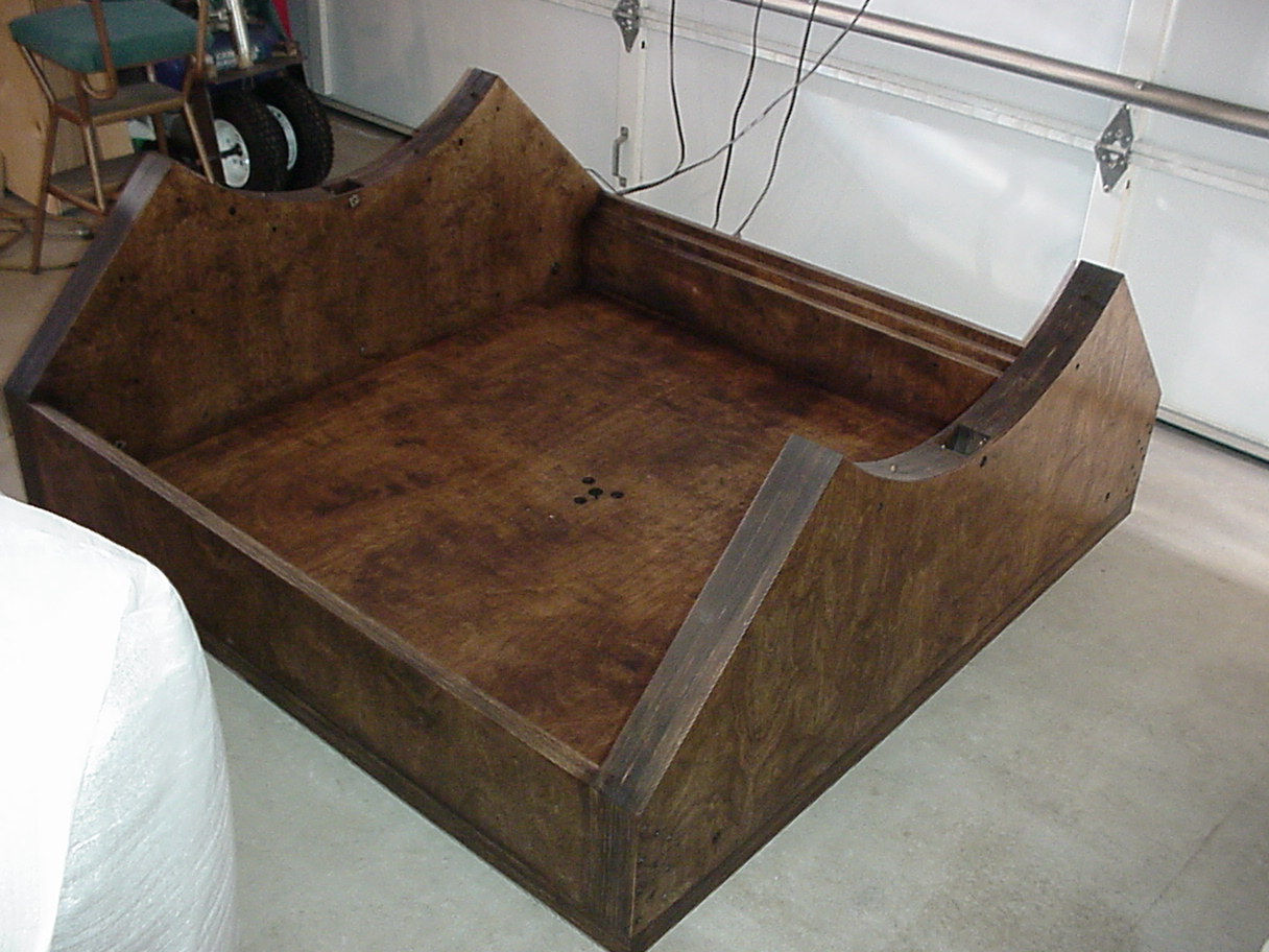
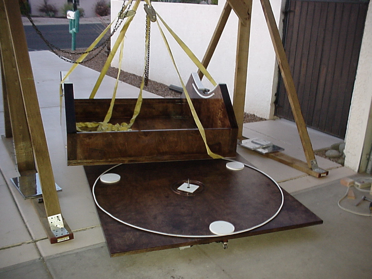
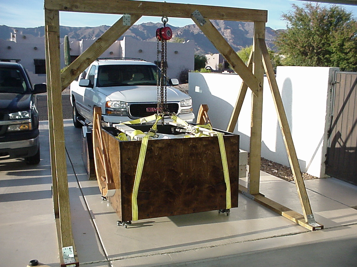
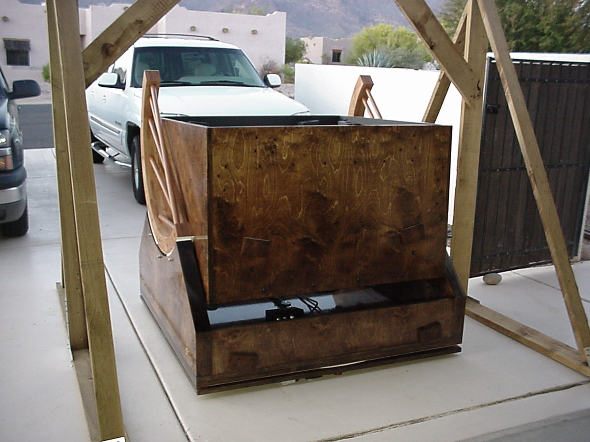
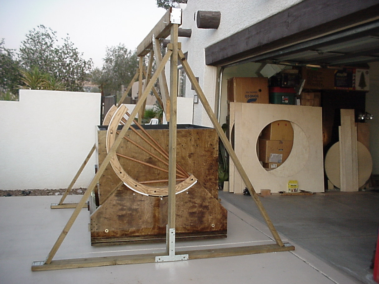
Now for the Rocker Box and Ground Board....


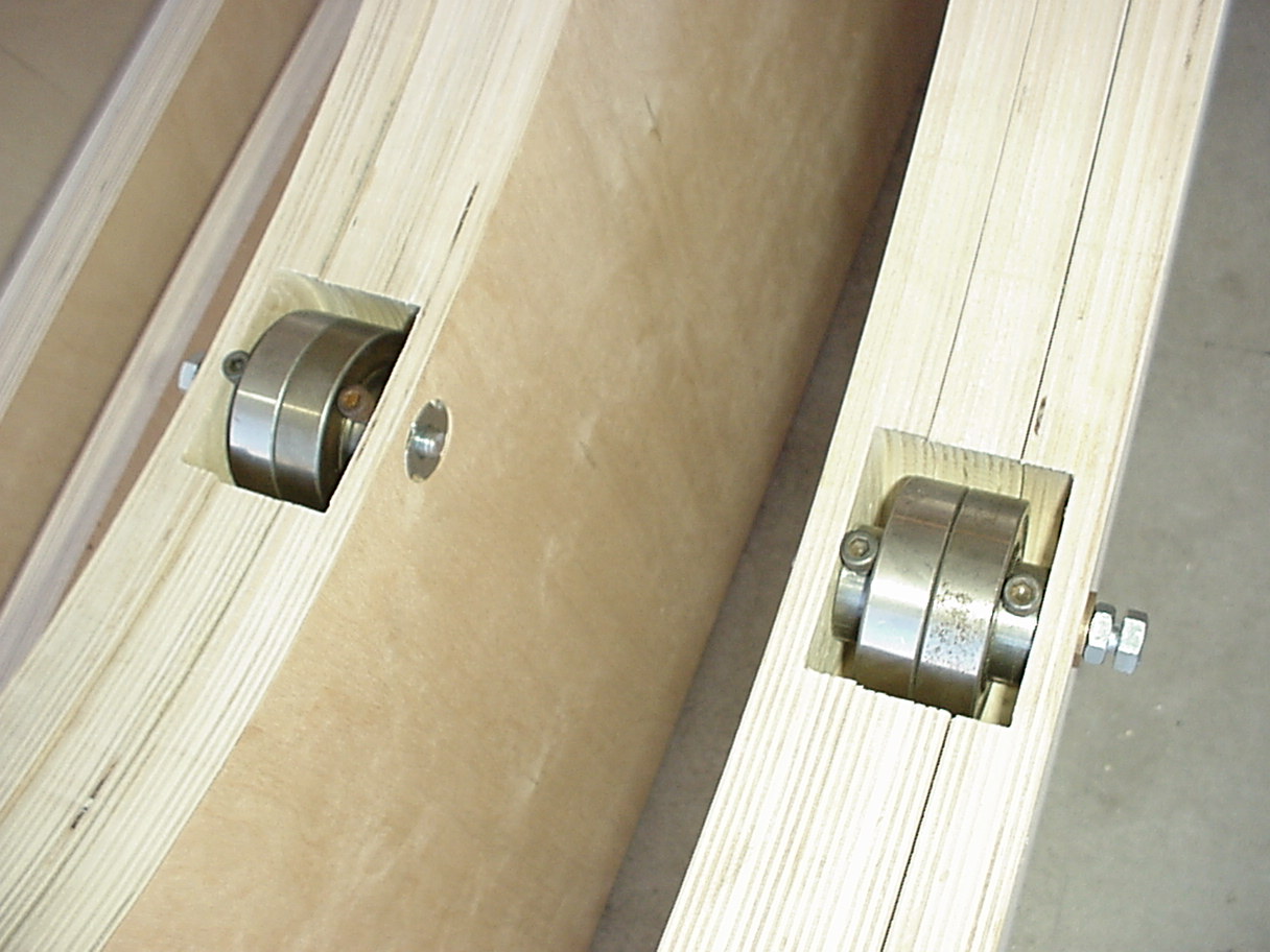
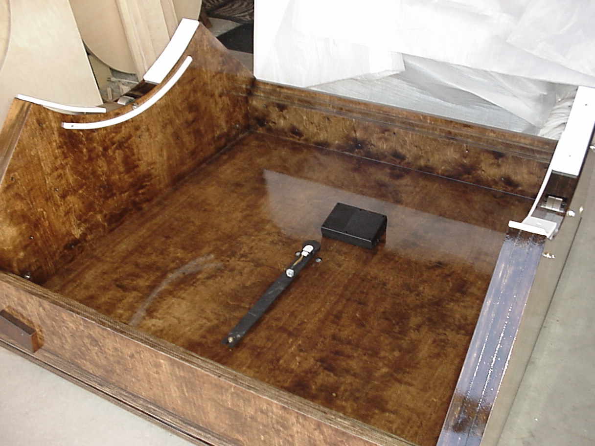
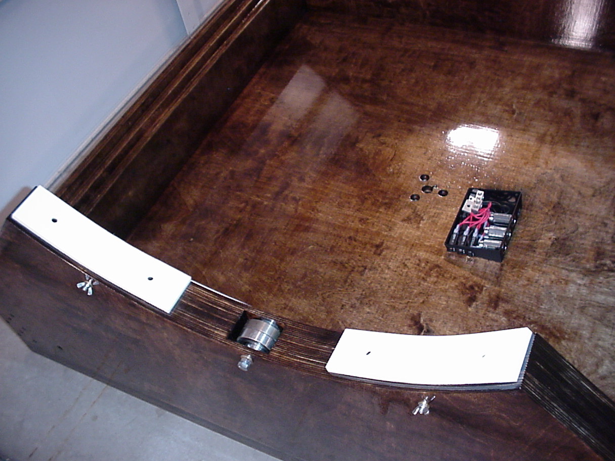
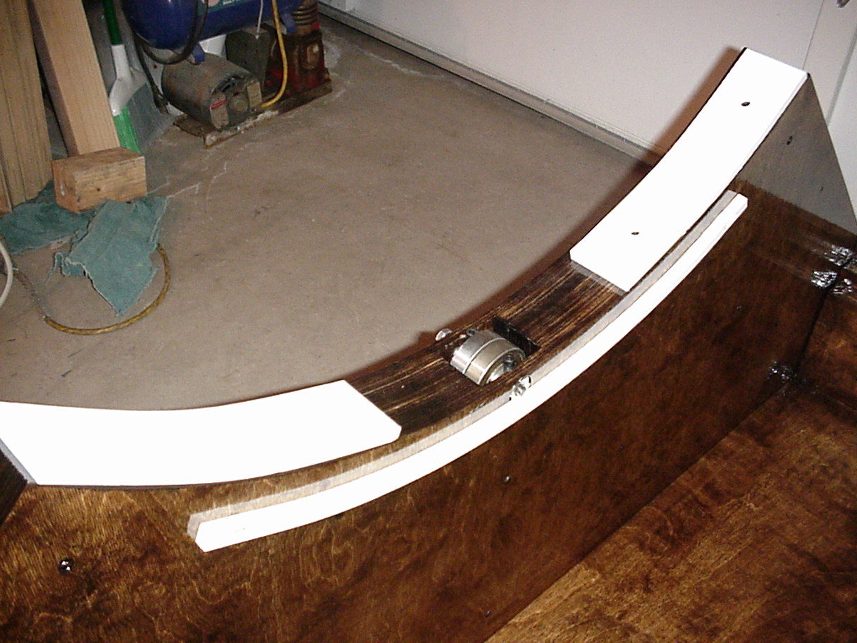
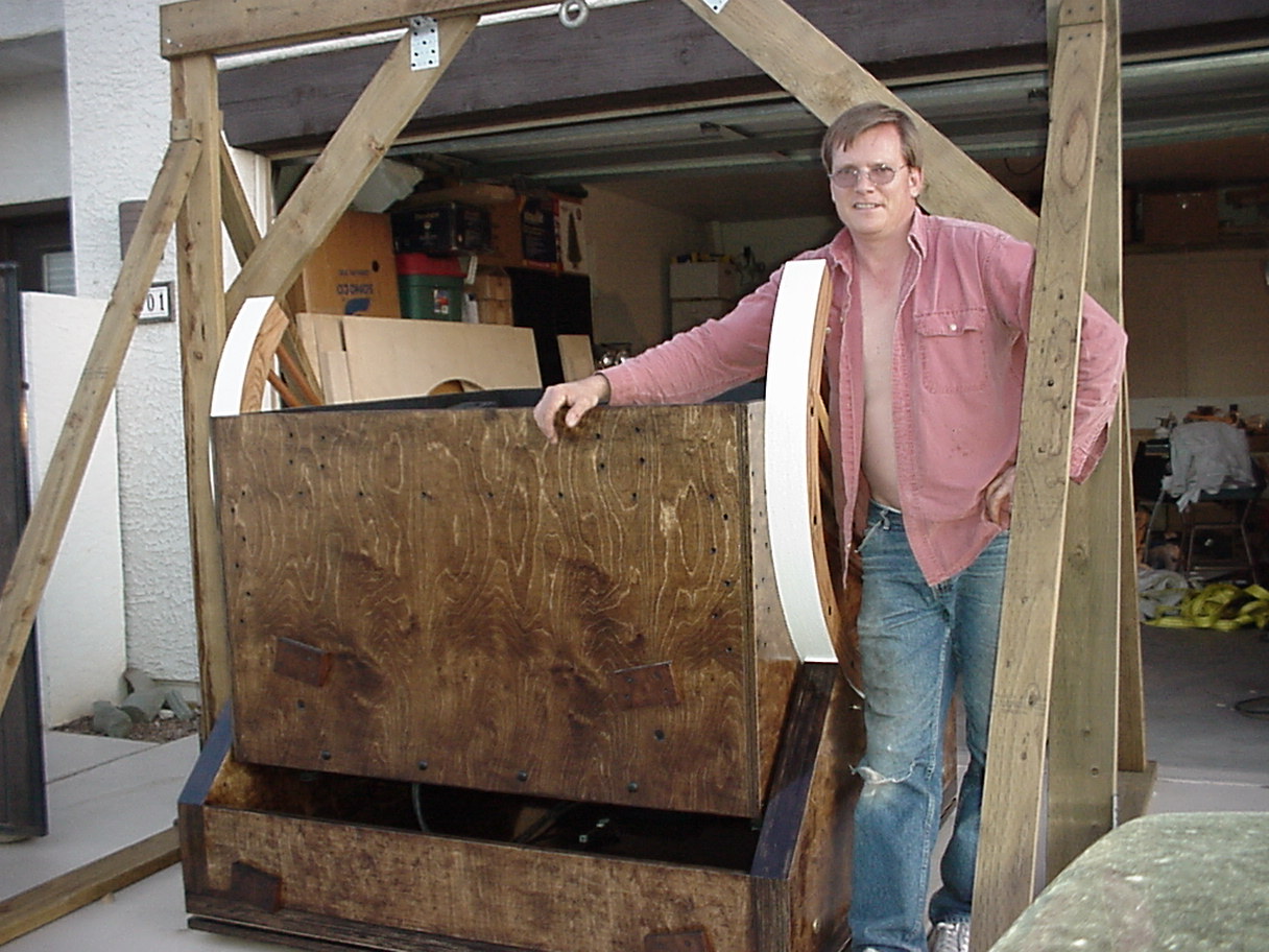
Rocker box sides with the lift bearings placed in there for fit.

Rocker Box Sides.jpg

___________________________________________________________

The rocker box floor had countersunk holes drilled for the 6" lag bolts and filler sanded flush after the bolts were installed....


Rocker Box Floor.jpg

___________________________________________________________

Here is a closeup of the lift bearings. Two 2.375 bearings are side by side on a steel shaft with an off-centered hole through the cylinder. With a slight twist the bearings will rise and make contact, lifting the Alt Bearing a small amount and relieving some pressure off of the Teflon and a jam nut to hold it there....


Alt Lift Bearings.jpg

___________________________________________________________

Three bolts which surround the center pin on which the scope pivots, will press their Teflon pads against an FRP plate on the Ground Board. This removes pressure off of the three 6" diameter Teflon pads to make the scope turn more freely in azimuth. The brass spring-loaded electrical connectors will ride on siver-greased copper rings as the scope turns thereby eliminating any cords. In the Observatory, underground power comes up underneath the scope....


Push Pin Lift and Spring Loaded Power Connectors 1.jpg

___________________________________________________________

Once the FRP was laminated onto the bottom of the Rocker Box I used whatever I had to press and make good contact. Once again you can see joints are stained. Everything was glued and screwed with excess glue wiped off using a dampened cloth. Stain was applied while the glue was wet since it will permeate the joint when wet but if allowed to dry the glue will seal the wood and no stain will penetrate...


Press Curing the FRP Bearing1.jpg

___________________________________________________________

Here the Rocker Box is stained. Only needs Urethaning and parts....


Rocker Box Stained.jpg

___________________________________________________________

Now Urethaned and parts assembled onto it....


Azimuth Encoder Mounted.jpg

___________________________________________________________

Closeup of the bearing lift system. Also, the two spring loaded pins that ride on the rings are seen in the electrical box and feed three lighter outlets each with a 20A breaker....


Teflon and Bearings for Altitude.jpg

___________________________________________________________

On the inside edge of each wall is a Teflon arc which has a recessed spring to keep the Mirror Box centered within the Rocker Box, so the two don't slide perpendicular to the altitude motion....


Spring-loaded Side Teflon1.jpg

___________________________________________________________

The Ground Board has the two silver-greased rings and within that is the FRP pad for the three pin-lift bolt/Teflon pads, as well as, the 6" diameter Teflon main pads and a foam capped with Teflon tape dust seal....


Finished Ground Board with Foam and Teflon Dust Seal.jpg

___________________________________________________________

A closeup of the copper rings. The four bolt heads seen secure a 1/2" steel backing plate that the center pin threads through....


FRP Push plate and Silver Grease Coated Electrical Rings.jpg

___________________________________________________________

The electrical wiring underneath the Ground Board is protected....


Ground Board Wiring Protectors.jpg

___________________________________________________________

A special A-Frame was built to lift the 350 pound Rocker Box to be able to slide the Ground Board underneath....


Lifting the Rocker Box for the Ground Board2.jpg

___________________________________________________________

Probably the last time I'll see the copper rings....


Probably the last time I'll see the copper rings.jpg

___________________________________________________________

The A-Frame was actually built to withstand much greater weight.... The Mirror Box/Cell/Mirror combined weight is around 800 pounds.


Strapping in 800 Pounds1.jpg

___________________________________________________________

After sweating bullets, the Mirror Box is on the Rocker Box....


Mirror Box on Rocker Box.jpg

___________________________________________________________

Uneventful lift was welcome....


Mirror Box on Rocker Box 2.jpg

___________________________________________________________

That was a good day....


Success.jpg

___________________________________________________________