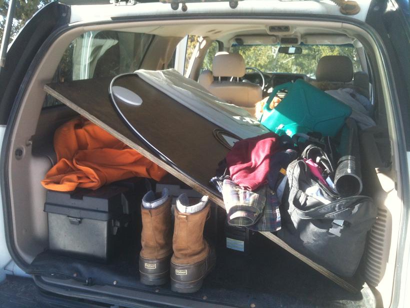
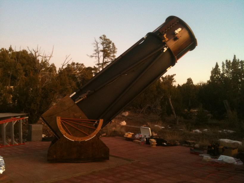
December 03, 2011 - August 30, 2014 (how many years to install?)
Tracking..., and GoTo.... Sounds good.
Things to note if you're considering ServoCAT;
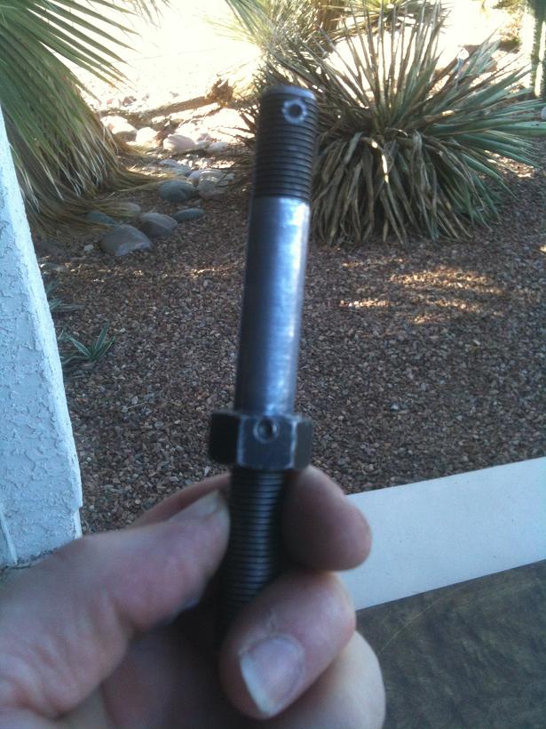
1. If your scope is larger than, let's say 30", you could be in for many hours of installation and potentially need better mounting hardware than what came with it requiring hours of shop time. You do have access to a machine shop, yes?
2. Remember to always click the radio button next to your scope name as there is a software bug which will not upload your values for ratio acceleration, speeds and could crash the scope and/or destroy the $500 motors, or, the almost as expensive gearboxes.
3. If you are using Argo Navis, you may experience, upon cycling power on ServoCAT only after the two-star is done, that you have no beeps. There is a software glitch which, upon rebooting ServoCAT that puts it in the wrong mode "skycomm" instead of the mode you want for Argo Navis which is "servocat". As such, in the wrong mode, and, no beeps, it has no better capability then SkyCommander and will drive to an object below the horizon where as with the right mode and beeps it would disallow such an action.
4. Digital Setting Circles.... SkyCommander is supported but can drive the scope into the ground. Argo Navis is also supported and has features to stop a bad goto from driving the scope into the ground, as long as the right mode is enabled.
5. The overcurrent protection built into the Az or Alt motors and monitored by ServoCAT may not always stop a bad goto..., causing the mirror box to climb right out of the rocker box. I've not experienced this but a friend has and the overcurrent value was so sensitive that one increment made the difference but the setting of Slew or Jog made a difference too....
6. Stay tuned Space Fans....
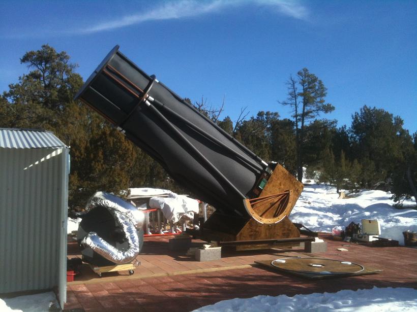
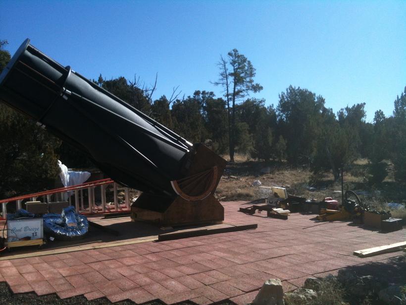
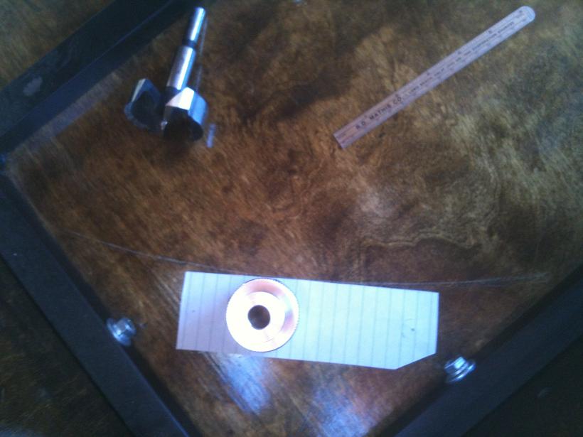
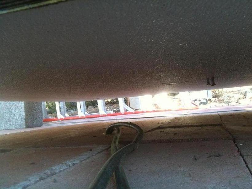
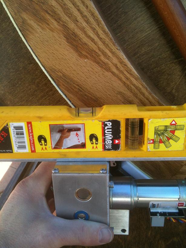
The scope had been built on a tight schedule, having first-light just one night before my friends flight arrived for the OSP party, so the mods needed for ServoCAT were not all implemented initially. So now I must router grooves for the steel cable which will eventually drive the altitude direction, but first I have to lift the scope up on one side. A 2 ton scissor jack was used to lift one side of the mirror box up 1/2".
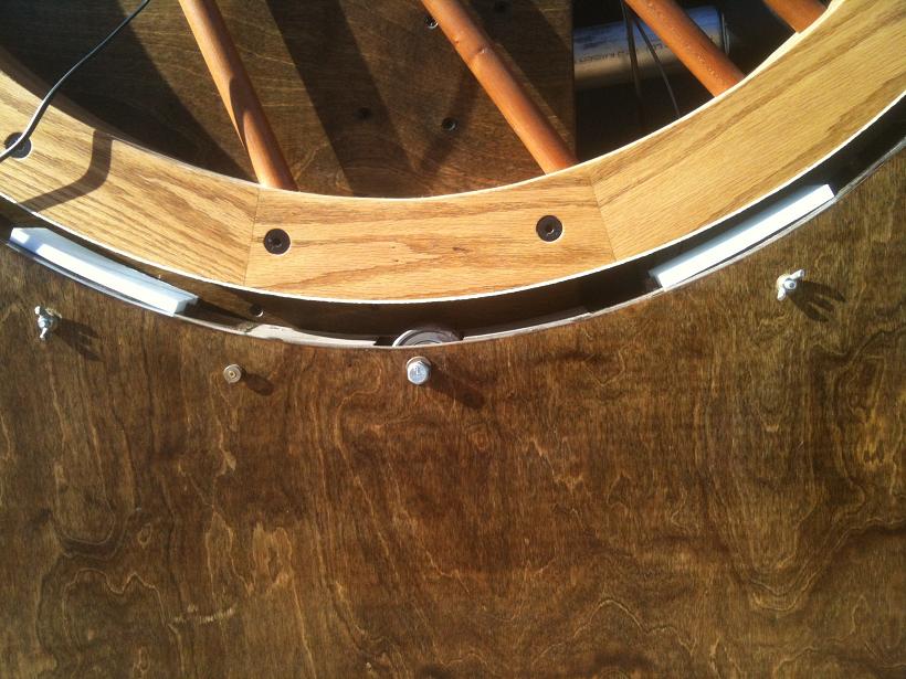
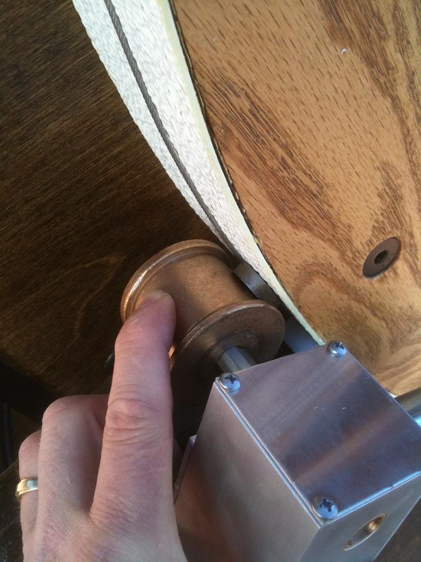
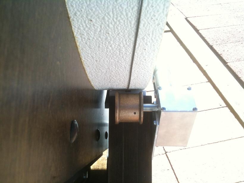
Between the pads resides a double roller bearing pair in a pocket. It is set-screwed to an off-centered cam to allow the bearings to pivot up and releive some stress off of the Teflon pads. The ServoCAT cable is placed in te groove of the Teflon and positioned between the bearings....
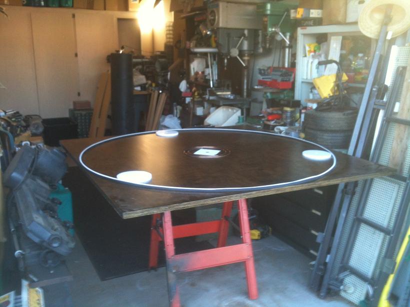
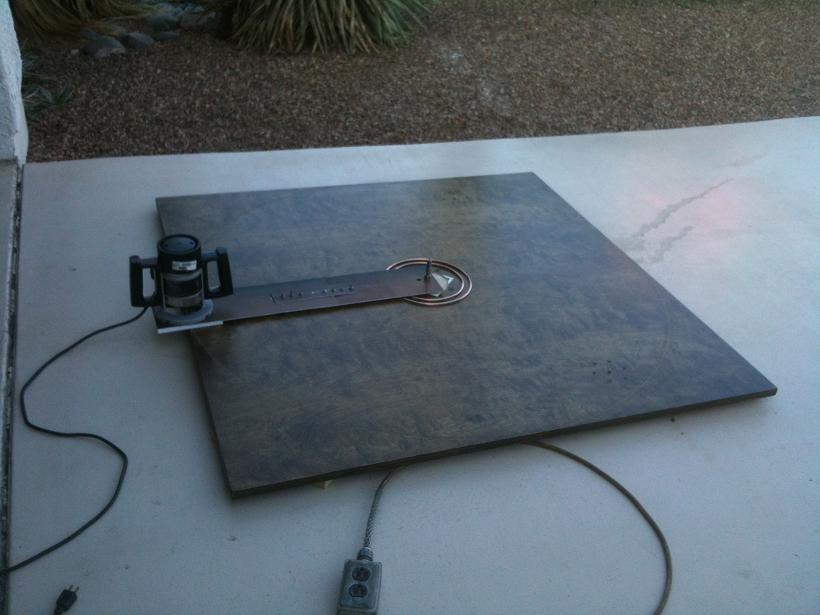
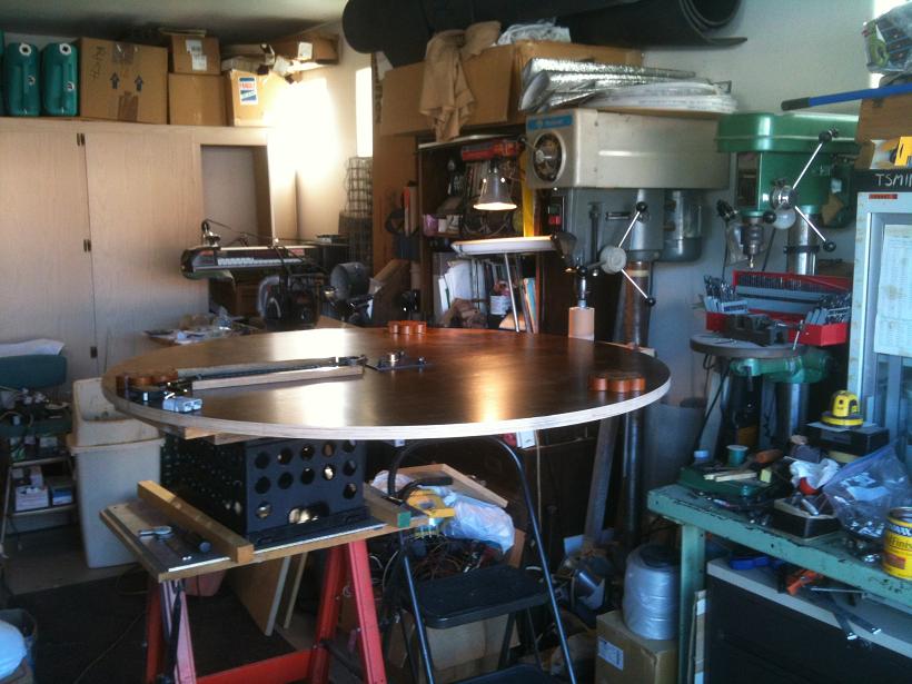
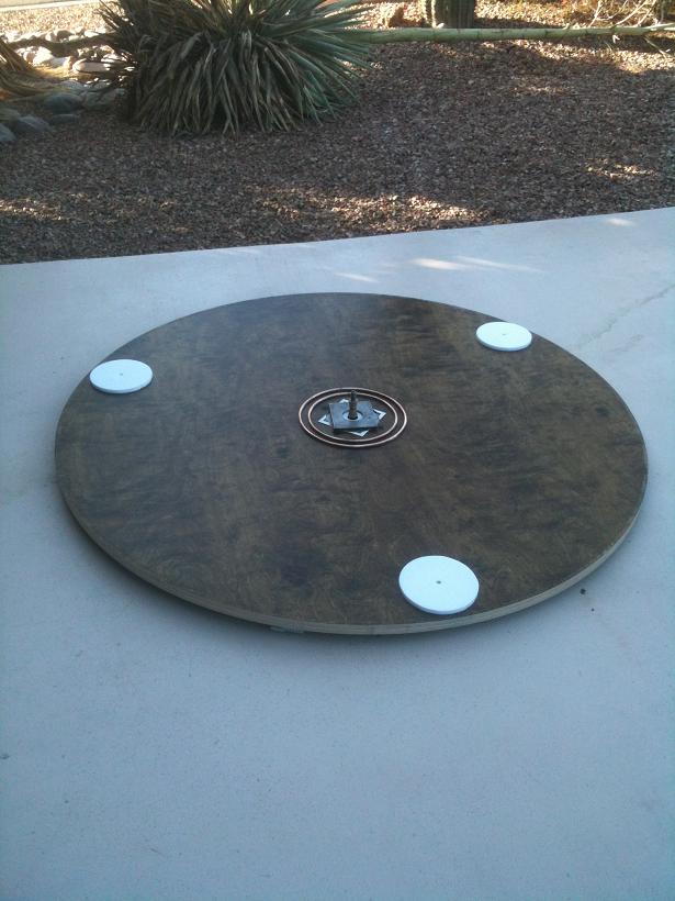
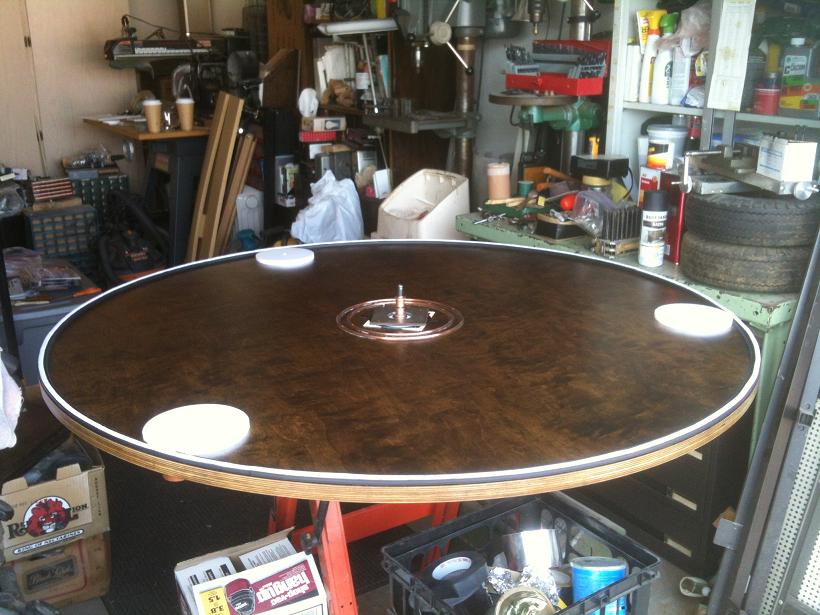
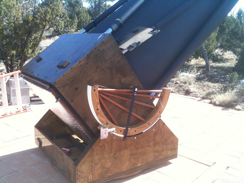
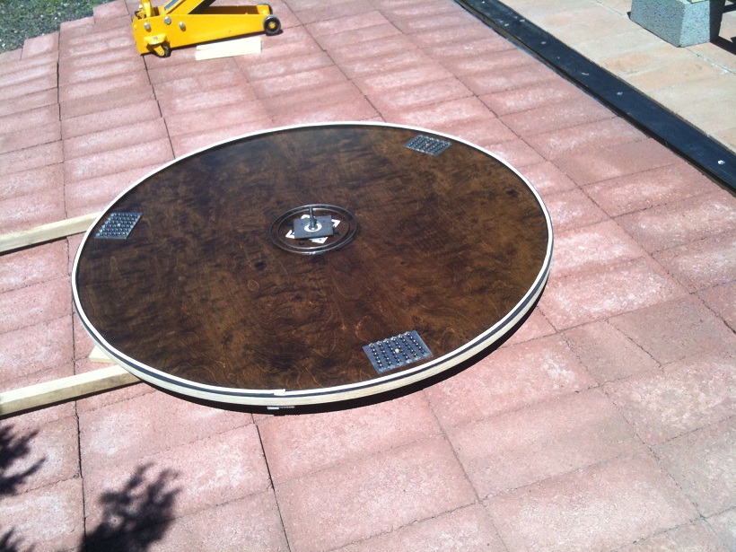
...But, next is to lift a 1700 pound telescope to get the 100 pound ground board out to make it round for use as the azumuth gear. ServoCAT will engage the perimeter....
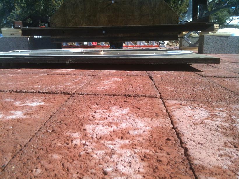
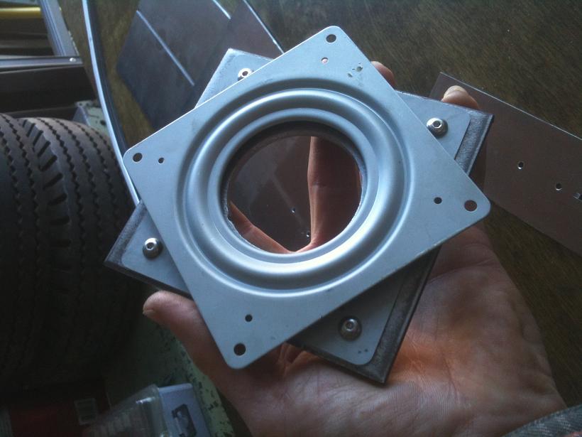
The previous system of lifting the scope at the center pin used three 3/8-16 bolts tipped with 2" diameter teflon disks. They surrounded the center pin and pressed against a 6" square of FRP. In five years the scope was operational the system worked but needing replacing if I was removing the ground board. The three bolts will now press on a 3/16" thick steel plate atop a 4" lazy susan greased bearings....
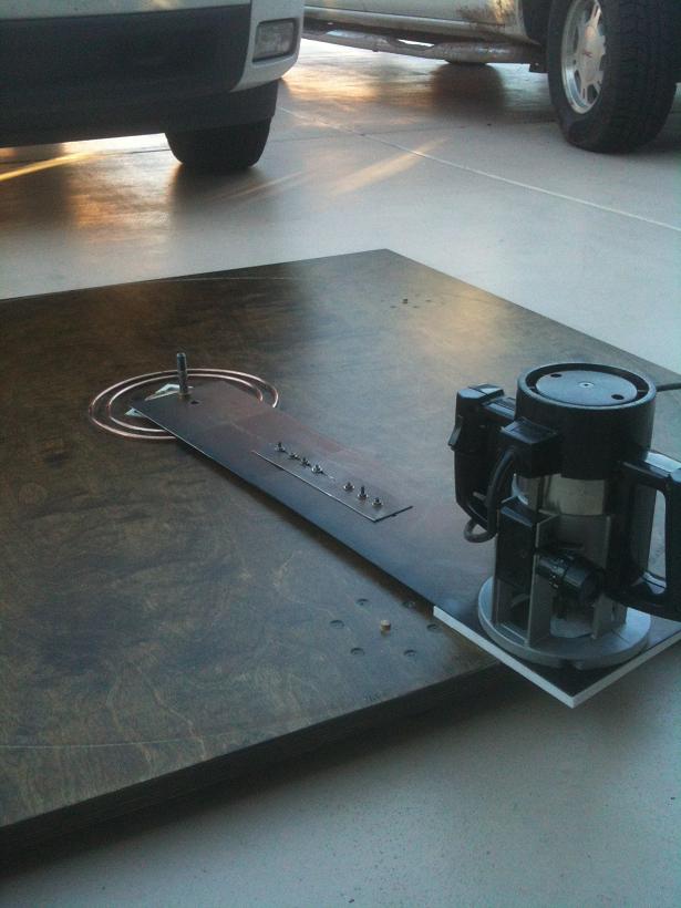
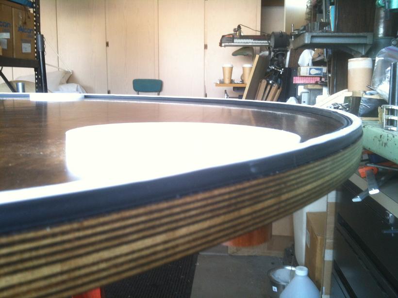
The gap between the rocker box and ground board is 3/8", so to allow for the extra thickness of the lazy suan and steel plate I routered out a pocket removing much FRP....
Teflon pieces were put under the jig to keep the screw heads from scratching the urethane, and a teflon plate was made to lift the router up 3/8" so the jig could pass over the three wood dowel pins used for the large teflon pads the scope rides on....
Eventually, it looked round. The 1/4" router bit had 1.125" long cutting length and a single pass was done to remove the corners at a speed of about 1/10" per second....
Next the fine grinding had to be set up. Using the same 3" diameter by 4" long sanding drum used for making the altitude bearings perfectly round all that was needed was a new plate, again with teflon pads to keep the ground board up to miss those dowel pins, pivot clamp and another to lock the pivot angle....
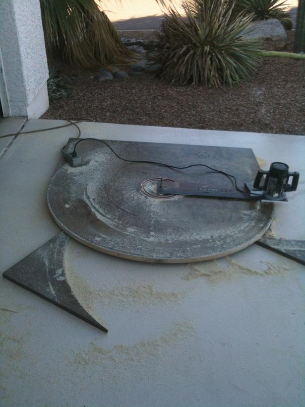
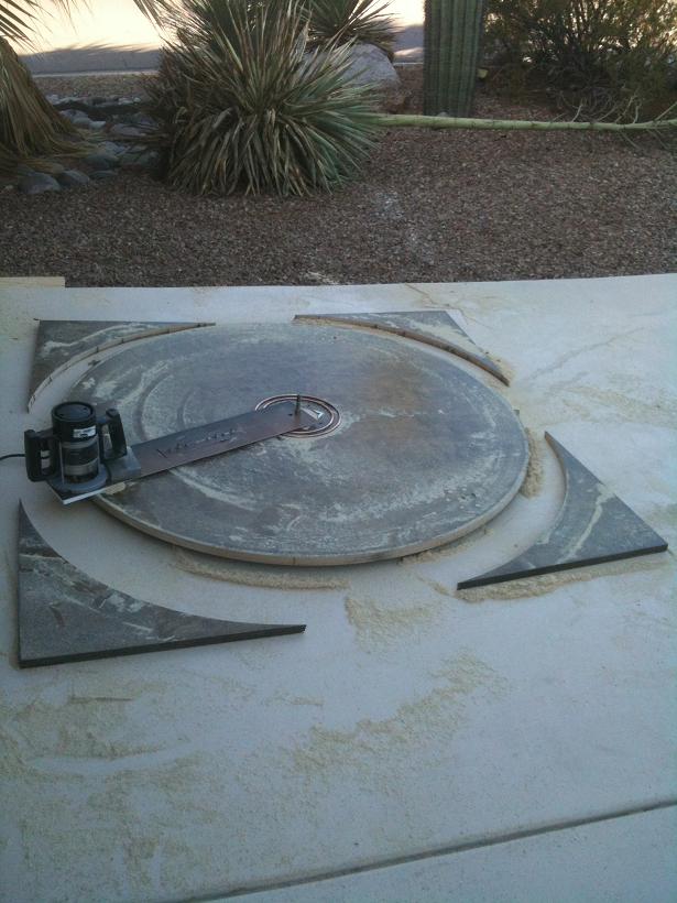
The plate was pivoted inward as the ground board became more round. Eventually there was uniform sound from the sanding drum and little sawdust made....
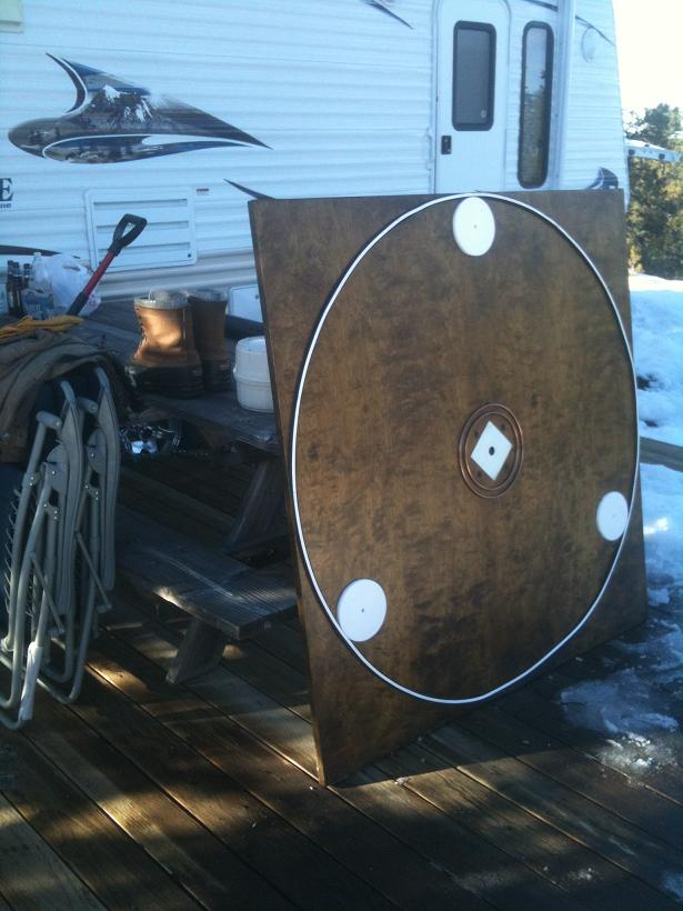
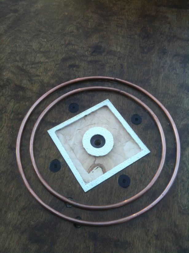
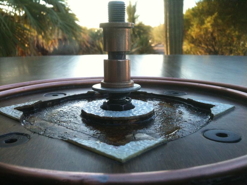
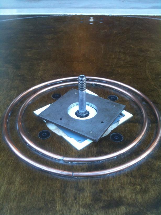
Once round and de-dusted, the parts were reattached. This is the center bronze support so the center lift system can transfer the weight to the ground. The center pin is jam-nutted to a 6" steel plate....
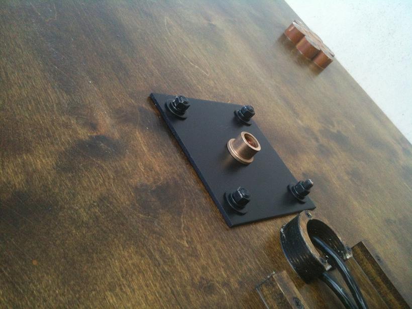
Next..., drilling the hole in the floor of the rocker box for the spline shaft of the azimuth motor..., but first I have to get the now-round ground board to the telescope without damaging the nice perimeter.
I first scribed an arc of the ground board radius on the rocker box floor in that one corner where ServoCAT will be mounted. I made a paper template of the Az motor mount to see how things lined up, new and existing to see the problems I'd have to work around.... This helped...
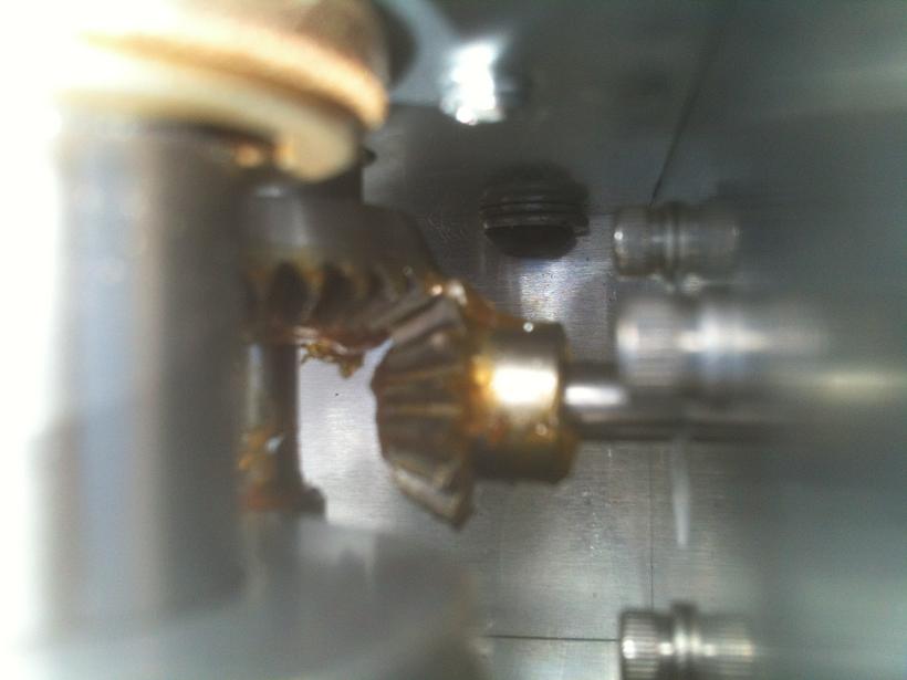
Using a 2" Forstner bit and a steady hand the hole for the motor shaft and gear was created. The plan was to have a 2" hole, 1/8" of ground board protruding into the 2" hole and have 1/8" extra for disengagingv the 1.75" gear... alignment was perfect!
Once the gear hole and 0.5" pivot hole were in I found the shaft wasn't long enough for the set-screws to reach, so I'll have to drop in new tapped holes for set-screws. With large scopes come custom made parts. Future versions of "Large Scope" parts will have a slightly longer motor shaft. I fortunately had drilled a 2" hole. If I had drilled the stated smaller hole I would not be able to get at the new set-screw locations to tighten them and the hold would have been large enough to attach the gear and drop the whole assembly in, but 2" was perfect...
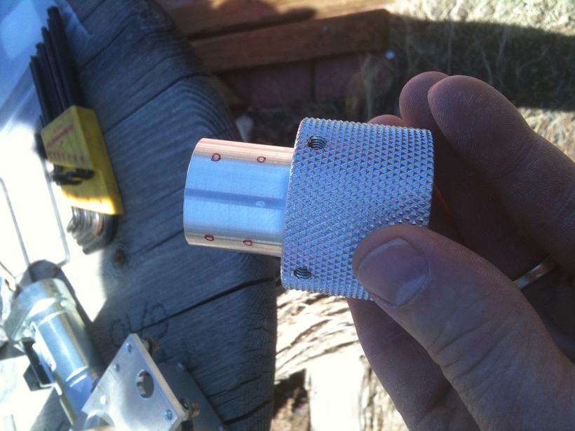
So, the Az motor assembly went in rather well, every hole getting stained and urethaned... Unfortunately the system is way under-designed for big scopes.... Three springs, each pulling 17 pounds each, is not enough to imprint the knurl pattern into 1"-thick Baltic Birch....
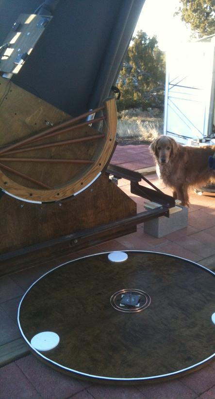
The copper rings got a fresh coat of conductive silver grease that the pins will ride on, and then I, with Kuiper (pictured) and Sagan (not pictured) watching, manuvered the ground board into position and lifted.
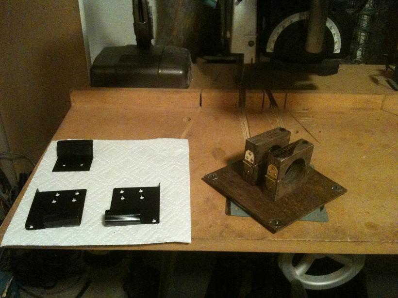
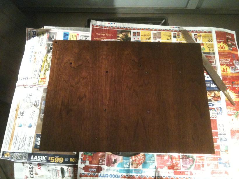
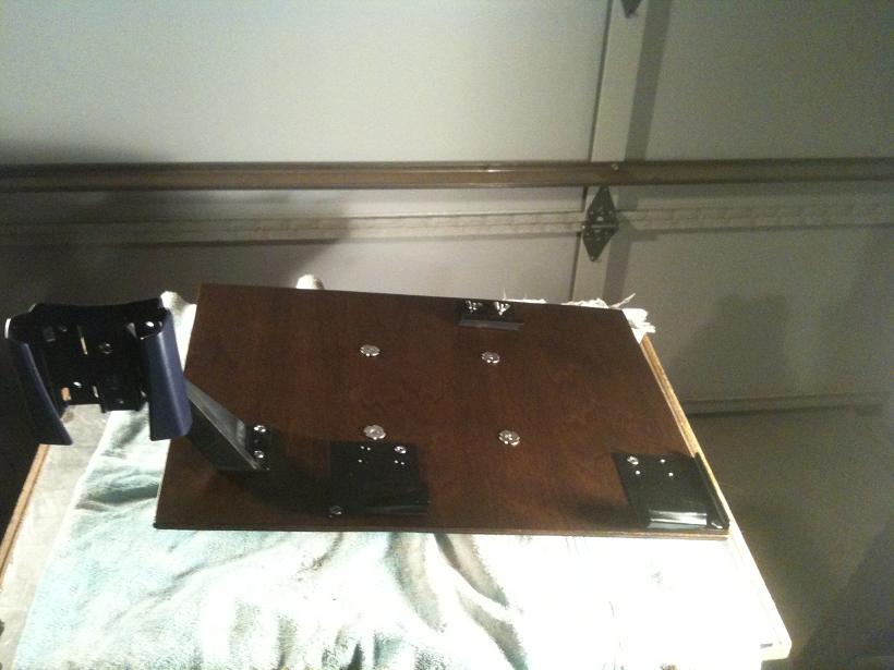
The computer plate would need upgrading to accomodate the newer laptop but instead I decided to build a new, thicker plate but use the same mounting hardware....
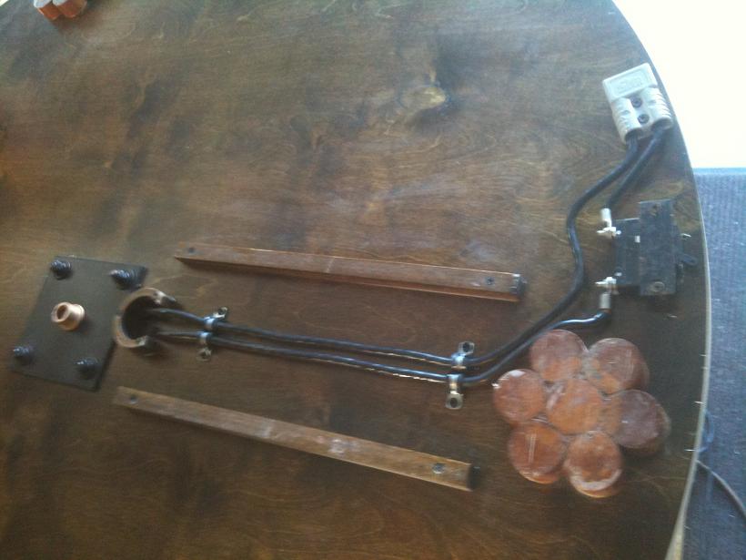
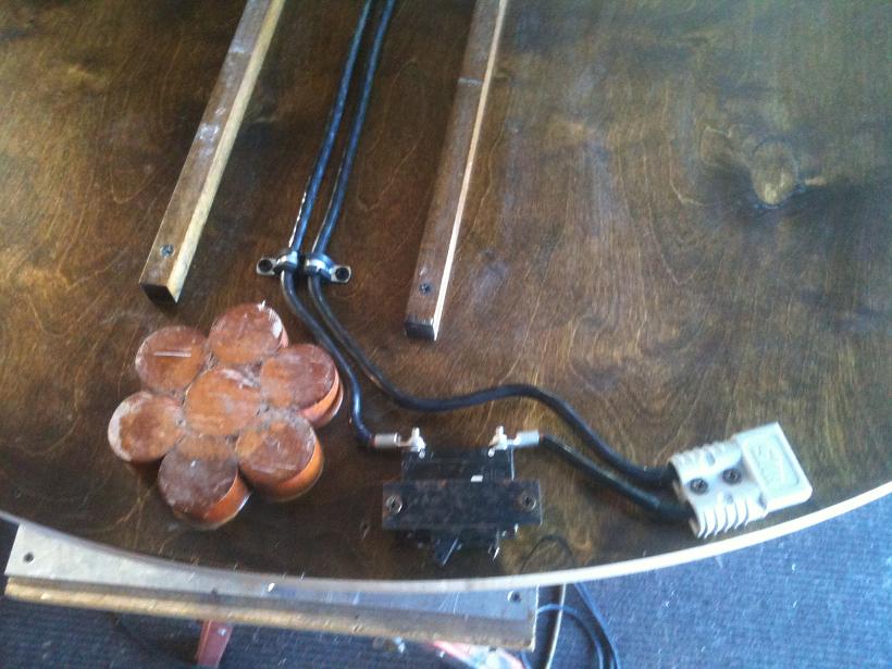
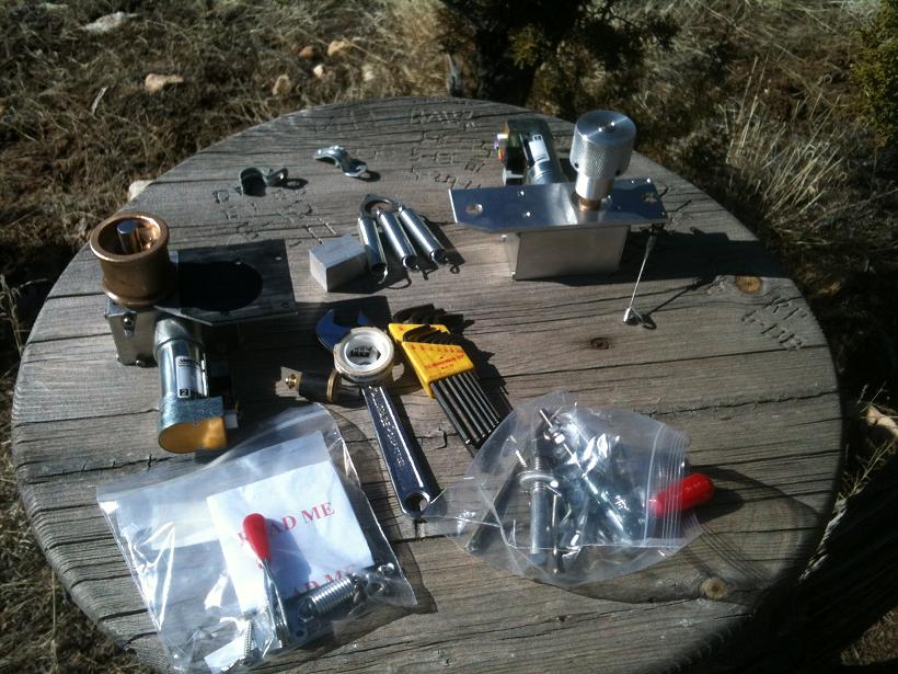
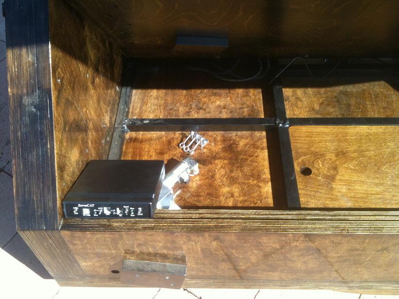
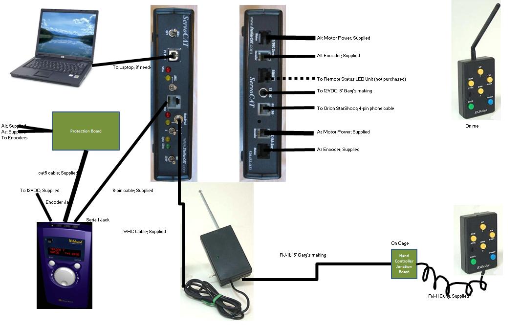
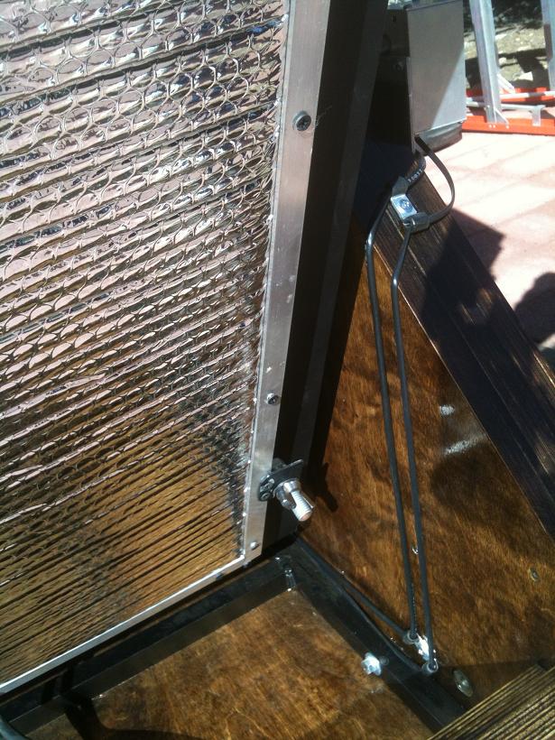
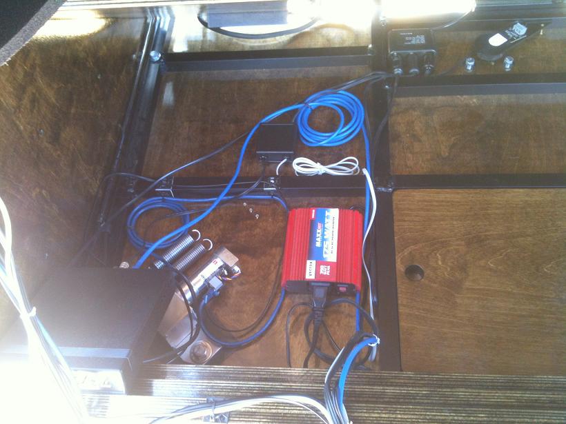
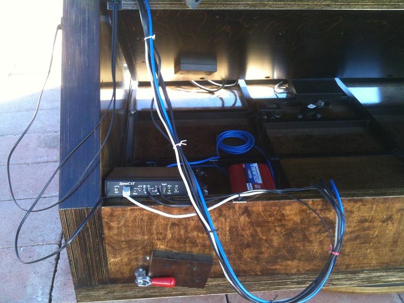
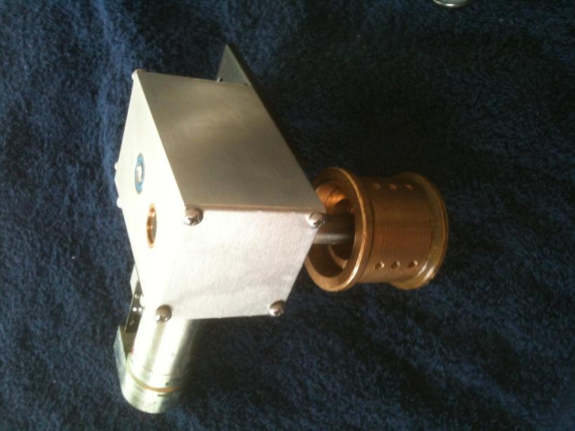
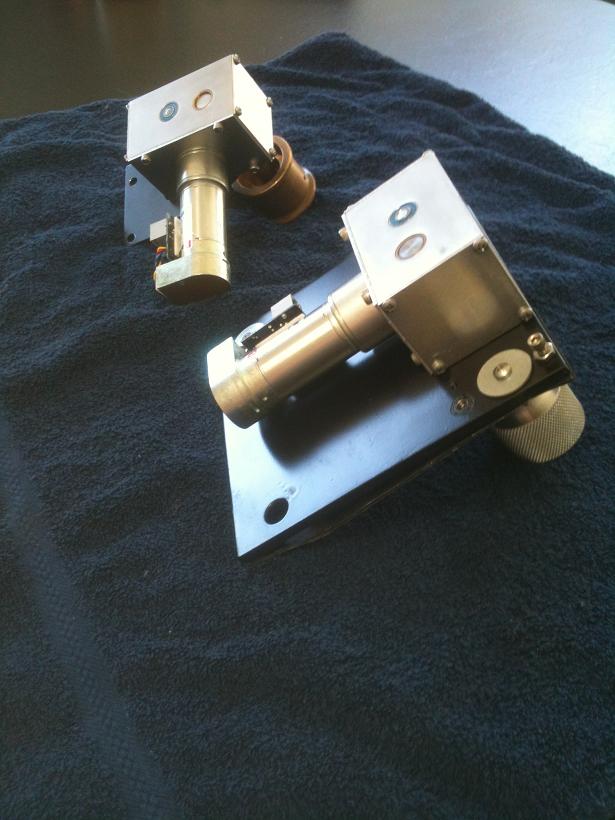
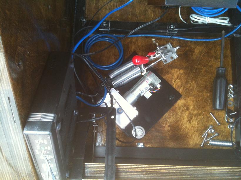
Wiring Diagram for ServoCAT. When Argo Navis and ServoCAT arrived and the shipping box was loaded with cables, I had to lay it out for my own understanding.... All the cabling was laid out and must still be routed securely.
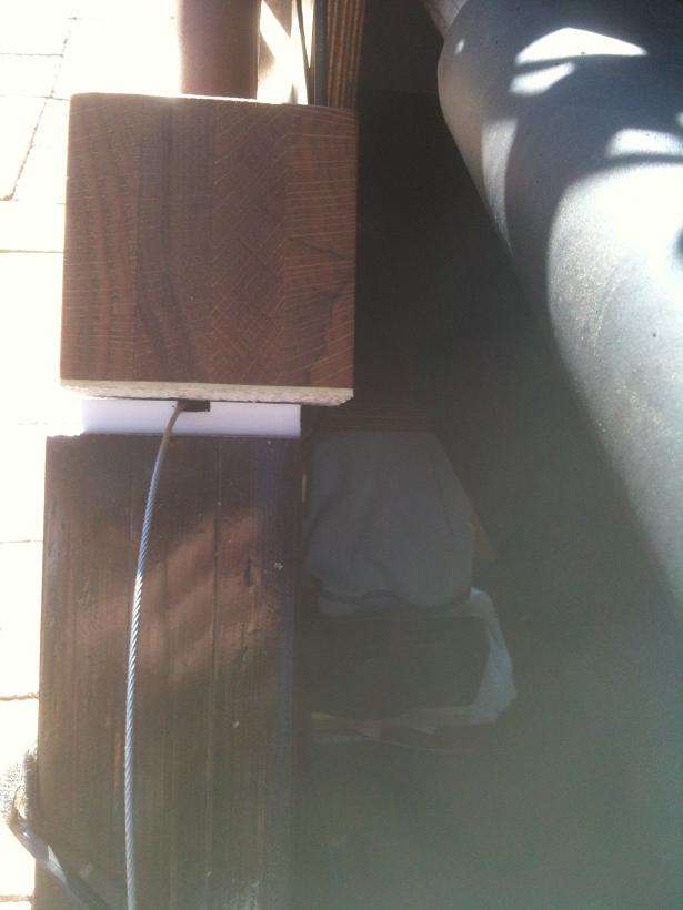
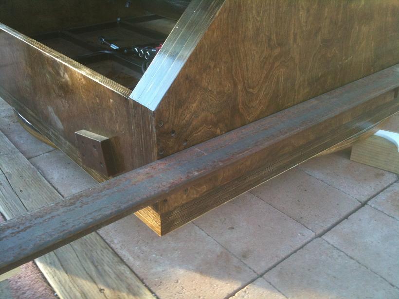
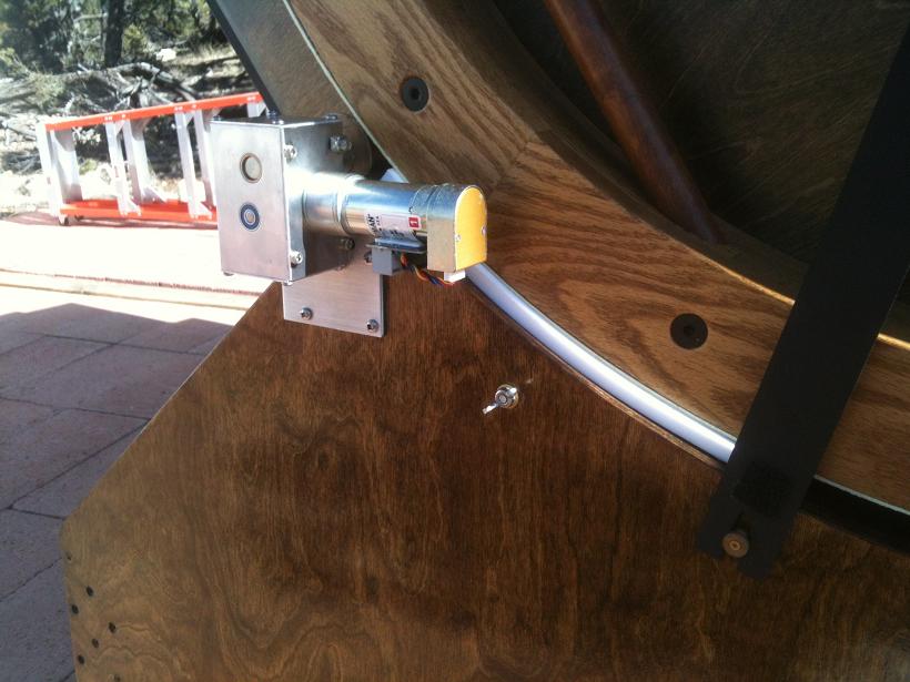
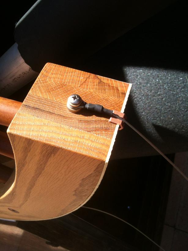
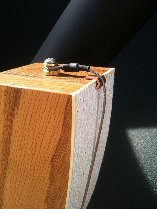
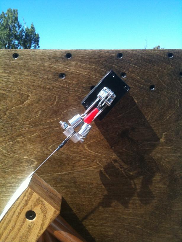
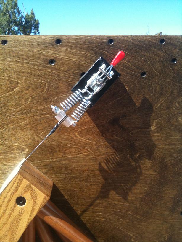
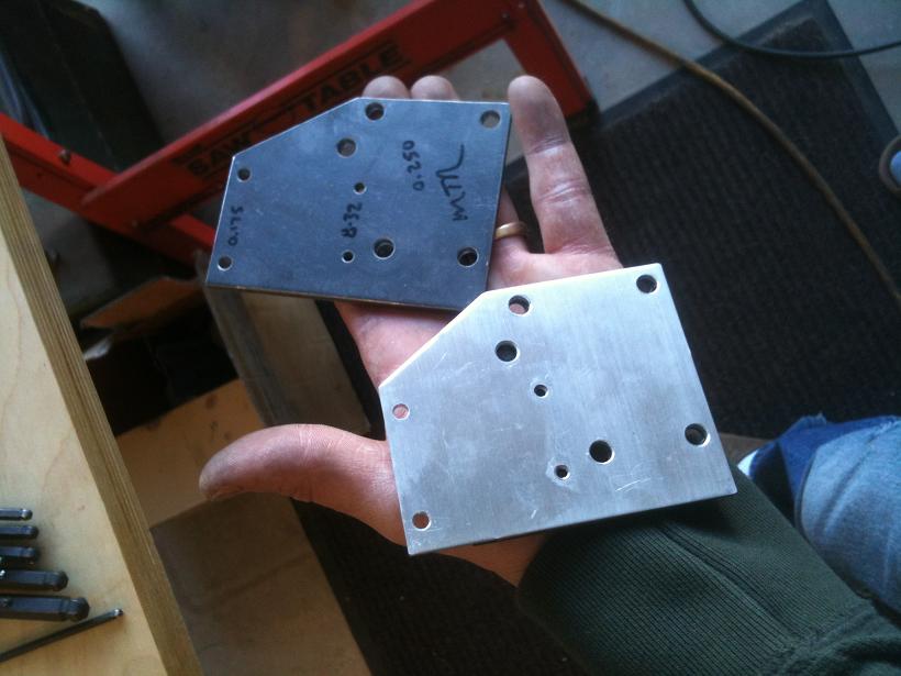
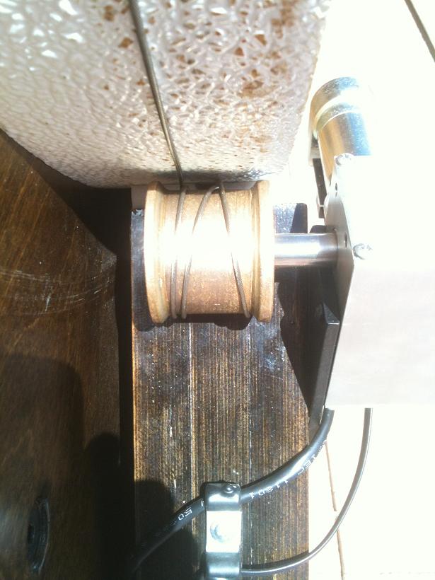
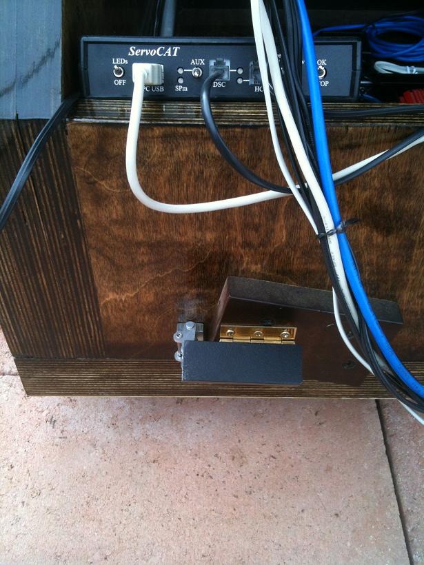
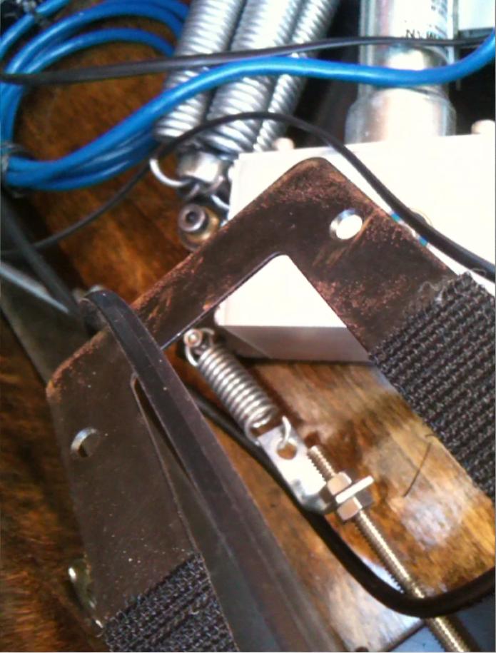
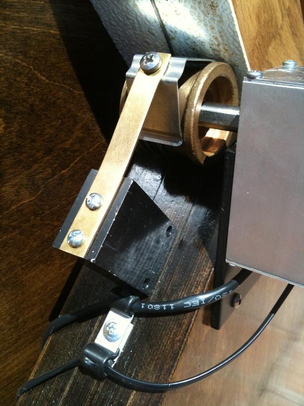
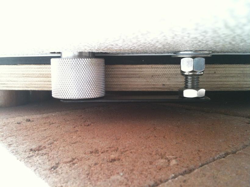
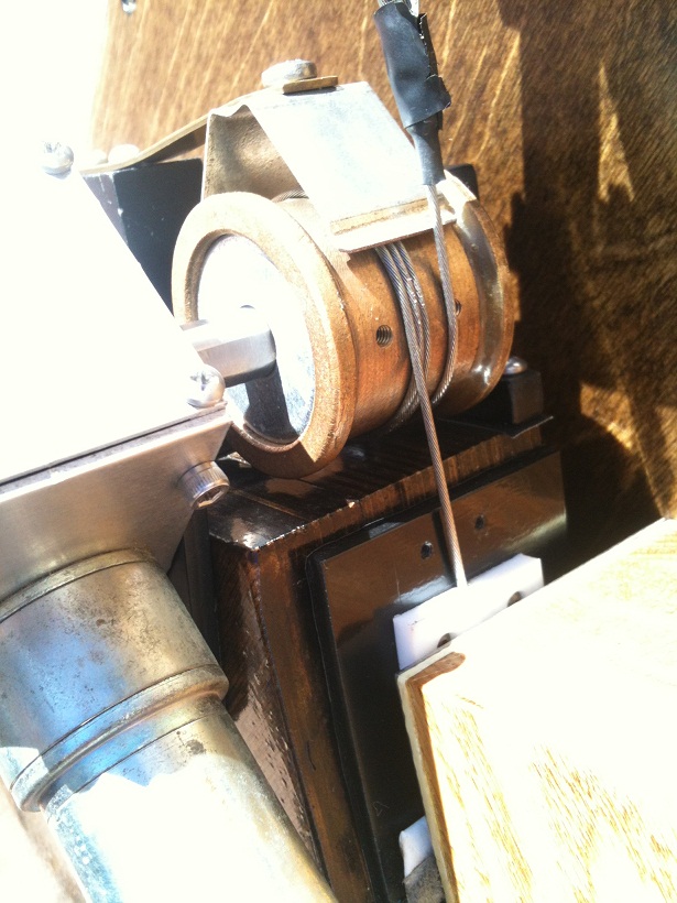
The other end of the cable will terminate at the clamp. Because of the thickness of the bearing, 3" thick Oak, and the gap between the mirror box and rocker box, three 0.5" aluminum blocks were cut and stacked onto which the clamp is attached. Each block is identical so that one could get the hole pattern needed for the clamp and if I ever replace the manual clamp with a motorized disengage I can bring the second block forward to the top and it can have its special hole pattern....
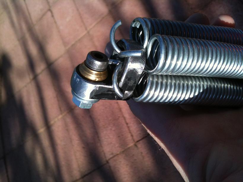
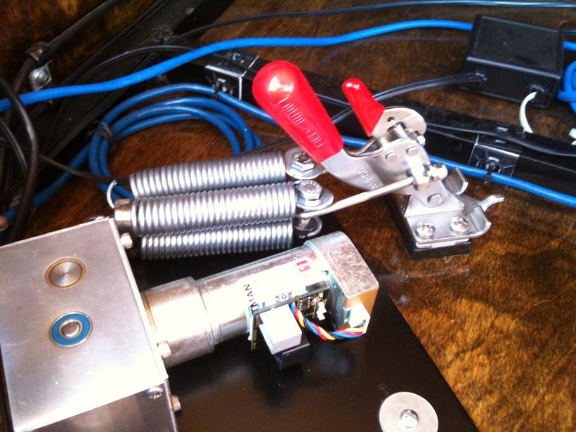
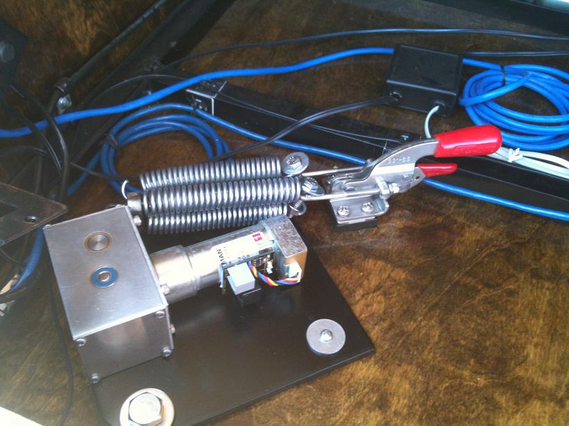
The Alt cable was terminated, though I did replace the spring that came with it with another, increasing the spring tension from 30 to 45 pounds force....
The upgraded spring was doubled because of slipping of the cable on the oil-impregnated bronze spool, increasing the spring tension to 100 pounds force....
And, I did go with three wraps of the cable on the Alt spool, not two.... Any extra drag was not noticable and it increased the friction on the spool by 50% since the force to move the scope in altitude is 50 pounds at the Alt bearing location.
With three wraps and 100 pounds force could the spool pull the cable to move the scope? No.... Not without bending the 1/8" aluminum motor mounting plate. So it got upgraded to 1/4" steel.
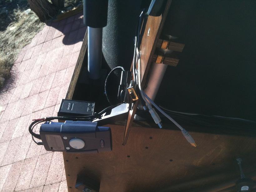
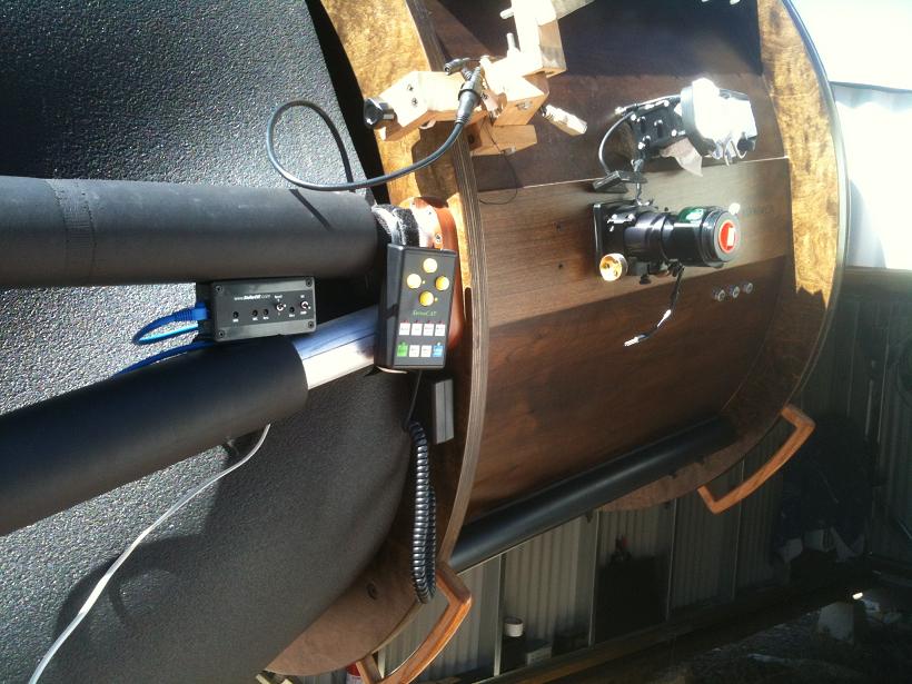
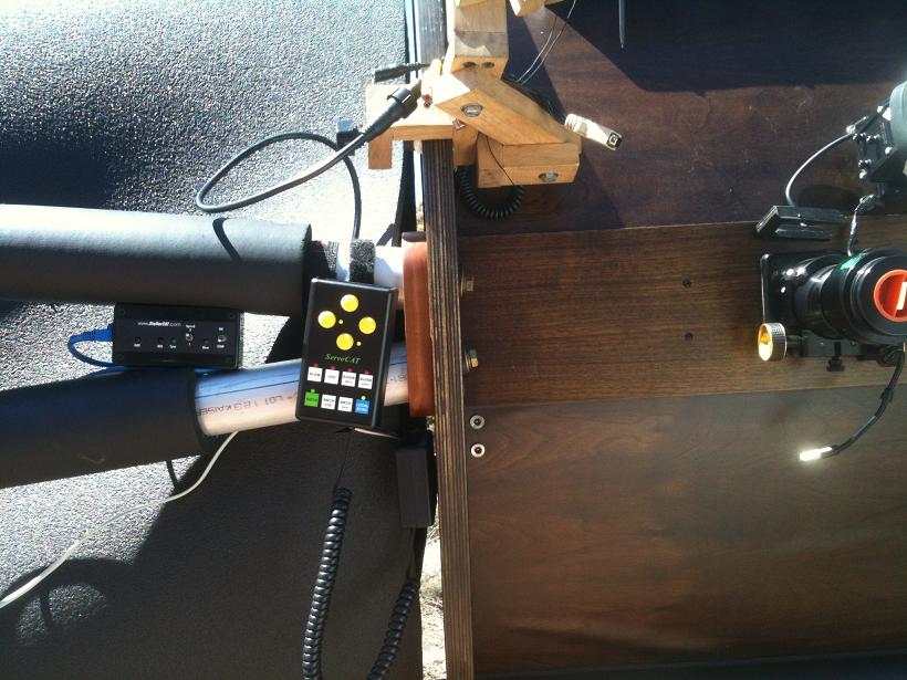
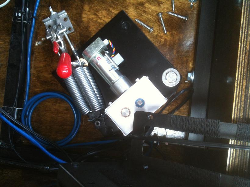
The wireless hand controller base unit was attached at the upper rocker box corner. This unit had been sent back to have its 30-foot transmitting radius increased to 100 feet because it's 25 feet just to the location of the future control room. With no other ServoCAT units at this location there'll be no interferance.
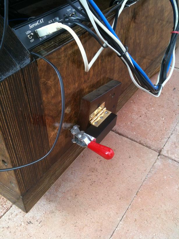
The hand controller unit was attached to the upper cage. The small junction pass-through board was installed in a small enclosure. This same enclosure also had a momentary normally open switch installed. The Remote Status Unit is also accessible when on the ladder.
This switch, when pressed then activates a relay which cuts power to ServoCAT. The reason behind it is that once the scope is pointed at the North Celestial Pole ServoCAT must be powered down and in speed position #2 when it powers up. I have the speed switch and a kill switch right there when NCP is in the crosshairs. After this the system is tracking making the two-star alignment much easier since the stars aren't flying by....
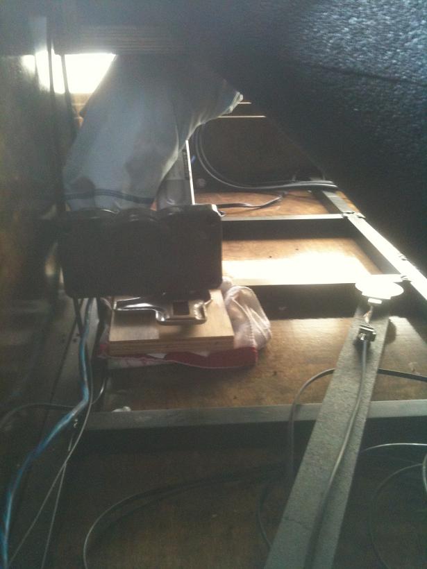
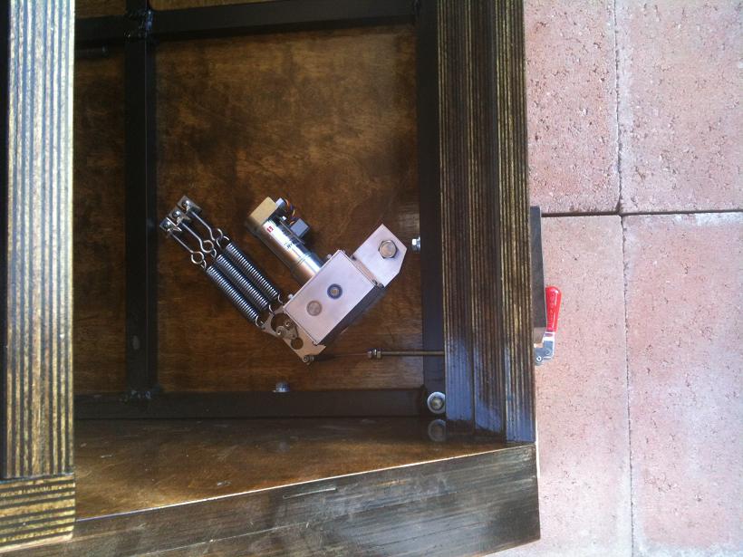
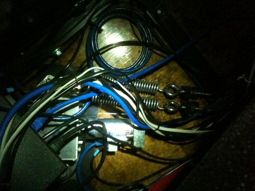
The wiring inside the rocker box is considerable, the kill switch relay box is above and left of the blue cat5 cable coil. The wiring harness has enough travel for the scope to move in altitude. All of this is to the left of the removeable step plate that I use when I have to step into the rocker box to remove or replace the mirror cover.
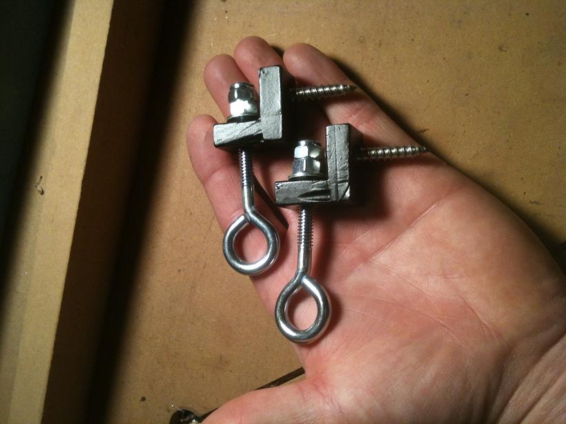
So, you see the three little springs are replaced with two big springs.... Roughly 50 pounds force increased to 100 pounds. Heavy-Duty angle brackets were made to anchor the eyebolts....
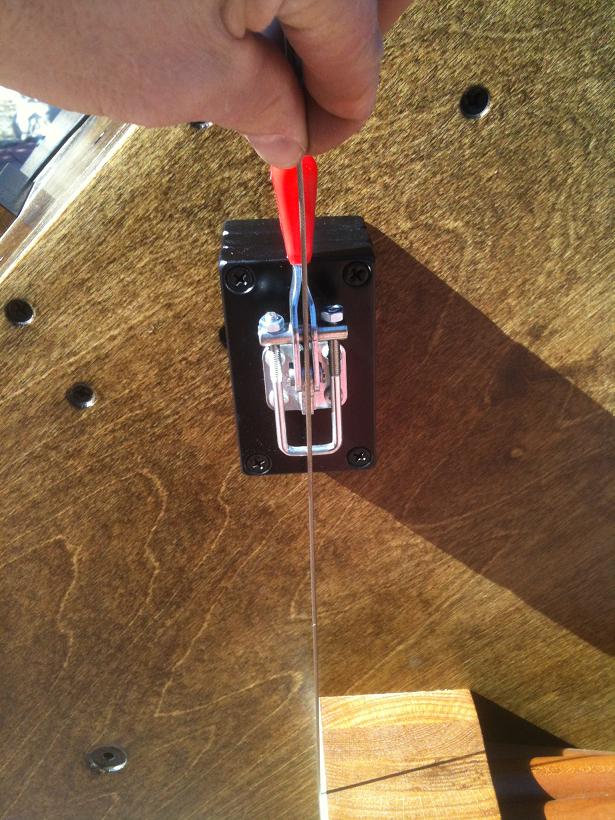
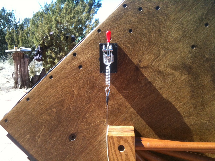
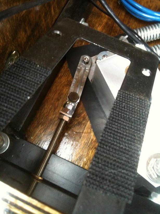
And, as expected, there was another issue in the install in that the lever would not stay disengaged.... A drop-down "keeper" was made so that when the lever was pulled back the keeper would drop down and prevent accidental engagement of the knurl as I manually moved the scope....
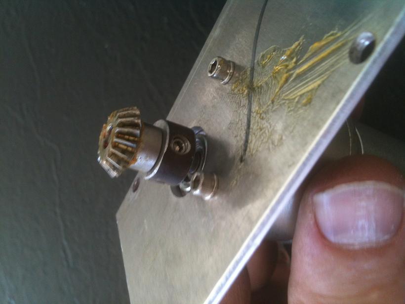
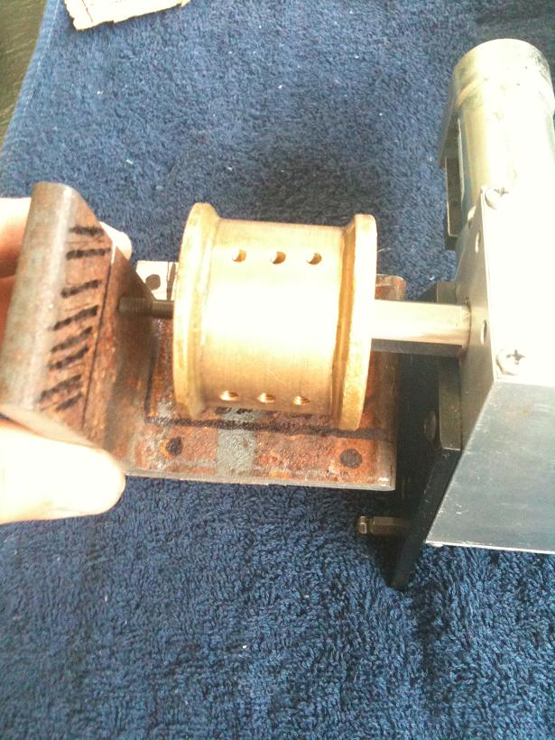
But, that didn't last long.... It was noted that the system was always coming up roughly 7.5% short in azimuth but perfect in altitude. In verifying the values in ServoCAT-Sky software I happen to find a software glitch. If you don't remember to click the black button next to your scope name the program will send wacky-values to the ServoCAT and if you thought it was going to move the scope at your programmed speed that might not match what wacky-value was sent. Same goes for acceleration. The now faster-moving, 1700-pound scope running with unknown acceleration value shoved the bevel gear on the alt axis up the motor shaft!!! I wanted 1.0 degrees per second with 10-second acceleration, I got much faster immediately!!! And, a lot of backlash and slop in the scopes tracking....
So that this would never happened again I made collars for both Alt and Az bevel gears, each with three set-screws around the perimeter. Three corresponding flats were filed on the motor shaft to keep the collar in place.., backing up that bevel gear.
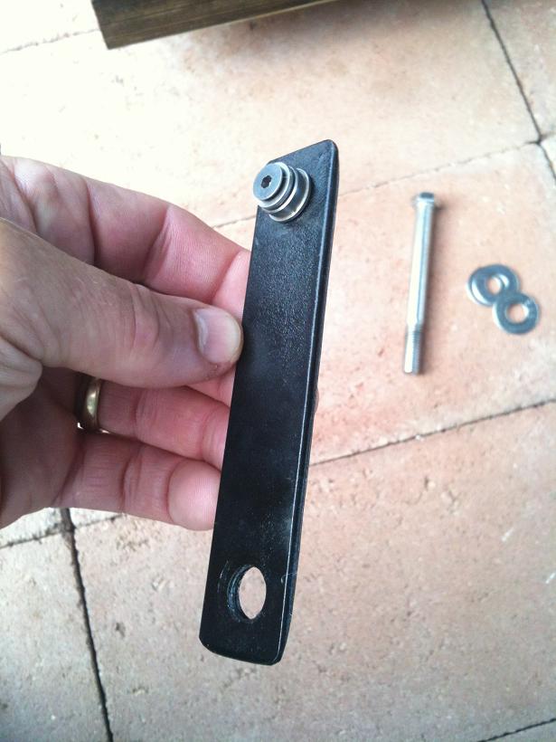
One thing noticed that I didn't like was that the Az spring, unlike the Alt spring, is always stretched, and super-stretched when you pull on the disengage lever. So, since I practically rebuilt everything other mounting hardware I bought a larger version of the Alt lever with a latching feature....
And once again I remade an aluminum motor mounting plate with 1/4" steel, because the spring pull direction is along the narrow dimension of the 1/8" aluminum plate which could tilt, or bend, with the knurl roller so far down the shaft acting like a lever....
Another issue noticed, actually noticed first on the knurl roller and remedied with extra set-screws, was that on the Alt spool there were just two small set-screws.... Four more were added since it was noticed that the first two had loosened some. That it's a oil-impregnated bronze spool, and small diameter set-screws, means that you can't tighten them as much as you'd like for fear of stripping the holes. With six set-screws there would not ever be another problem.
With the roughly 7.5% loss in azimuth goto's regardless of Az goto length, it was thought that the Azimuth must be slipping, so the two springs were doubled to four for the latching lever to pull in. Roughly 165 pounds of force..., and one of the heavy-duty angle brackets was modified to accept the four springs.
When the main springs are disengaged, there's a steel plate and another spring to pull the plate with the motor and knurl away from the ground board edge....
So, there's been a long gap in the installation timeline due to winter in the elevated desert, but at least the code download was successful after a windows driver was at fault. With the right code downloaded the GoTo's make it to an object without having to hit the button a second time when it was coming up ~7% short in Alt but making it to the right Az amount. Surprizingly, and very thankfully, getting any object within +/-7.5 arcminutes of center (my lowest power is 32 arcminutes)...!
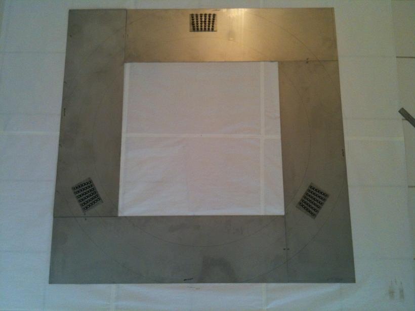
The Az force is 20 pounds at the knurl gear and 4 pounds at the eyepiece, once the steel insert frame was installed in the rocker box and the reinforced lazy susan bearing ring put in the center lift system. While the issues were sorted out I bought four rectangular stainless plates to attach to the underside of the rocker box in an end-to-edge fashion so within the box-shaped stainless would be a large anough area for the roller bearings to use as a race.
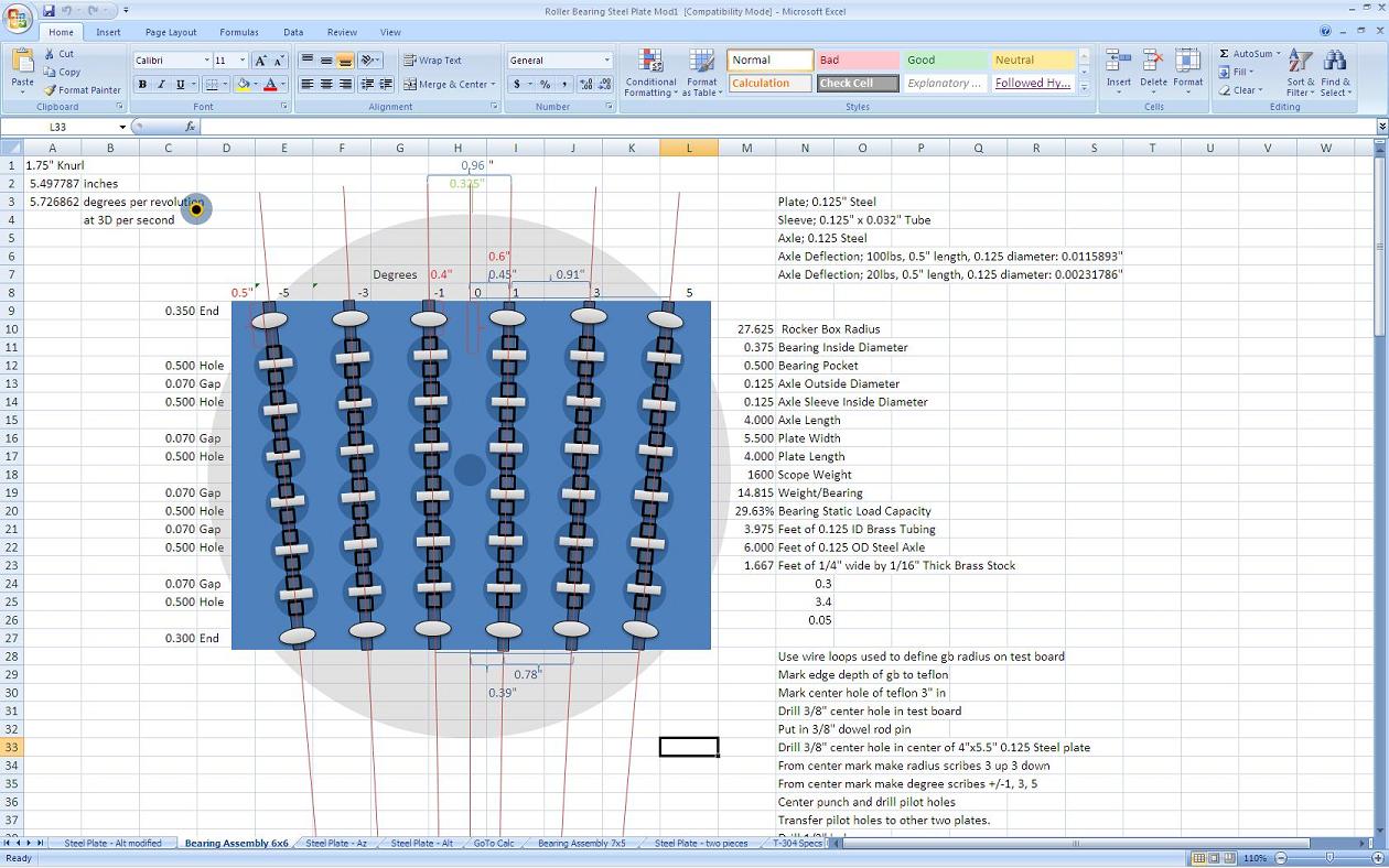
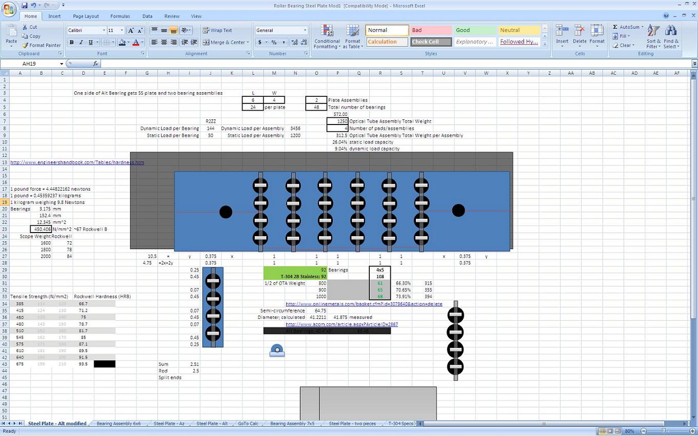
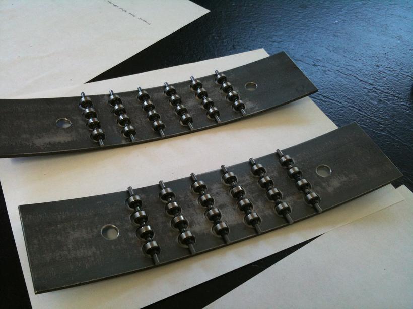
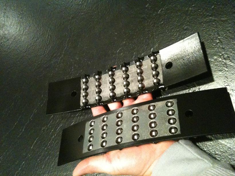
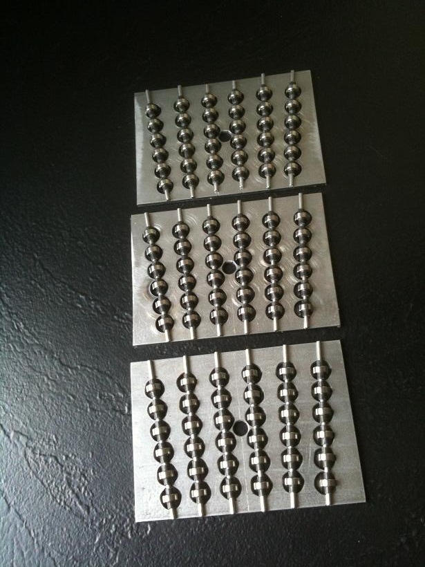
In Excel, my favorite design software, the parts were made of 0.125" steel plate, 0.125" steel rod for axles, and 0.375" roller bearings. The goal was to create direct replacements for the existing teflon pads and not raise the scope, so the overall height of the assemblies is actually 0.380".
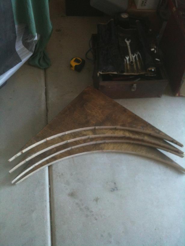
However, the Alt is 30-45 pounds force at different elevations, due to not perfect balance, and 1.5 pounds at the eyepiece (Ax is 4 pounds, so not a good match), but the roller bearing lift system between the teflon pads is so high the Alt bearing now teeters on the bearing and the wobble back and forth to touch either teflon pad is a problem. I needed to have less force at the SC spool so not to damage a gearbox, yet, have 4 pounds at the eyepiece, so, another roller bearing design was done, this time as arcing assemblies to replace the Alt teflon pads....
J.B.Weld was used to adhere all the spindle ends on all the bearing plates, then, a thin sheet of teflon-coated fiberglass sheet is used to prevent paint transfer since they'll be under ~350 pounds for each assembly....
So, now things are ready to install! The roller bearing lift will not be used on this side of the scope as the full weight will press on the new bearing plates. A stainless strip will be attached to cover the existing FRP as the race for these new curved bearing plates, which will provide zero friction. The drive side will, for the moment, remain as teflon/FRP with that sides' roller bearing lift system used to adjust overall friction and hopefully have less force at the SC spool....
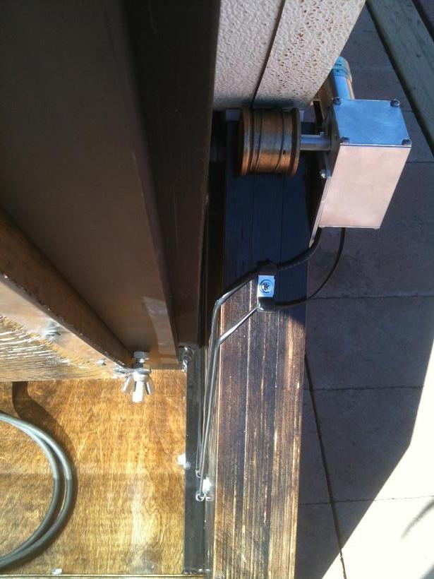
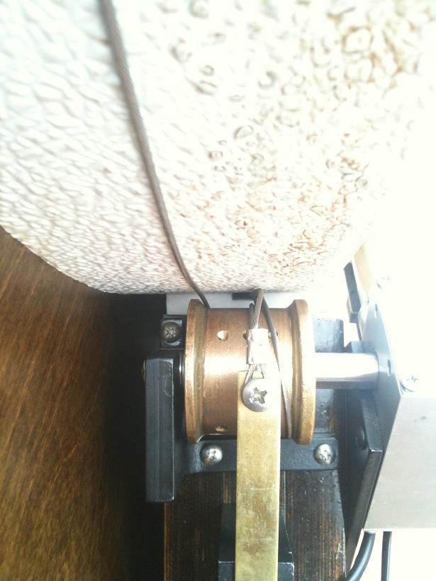
One problem I was continually having was the Alt cable would wind over itself. There needed to be enough slack for disengaged movement and even with just barely enough slack it would still strangle itself, so, I built a clip structure to keep the three winds in order.
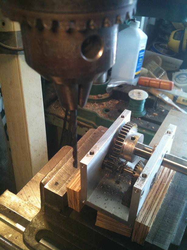
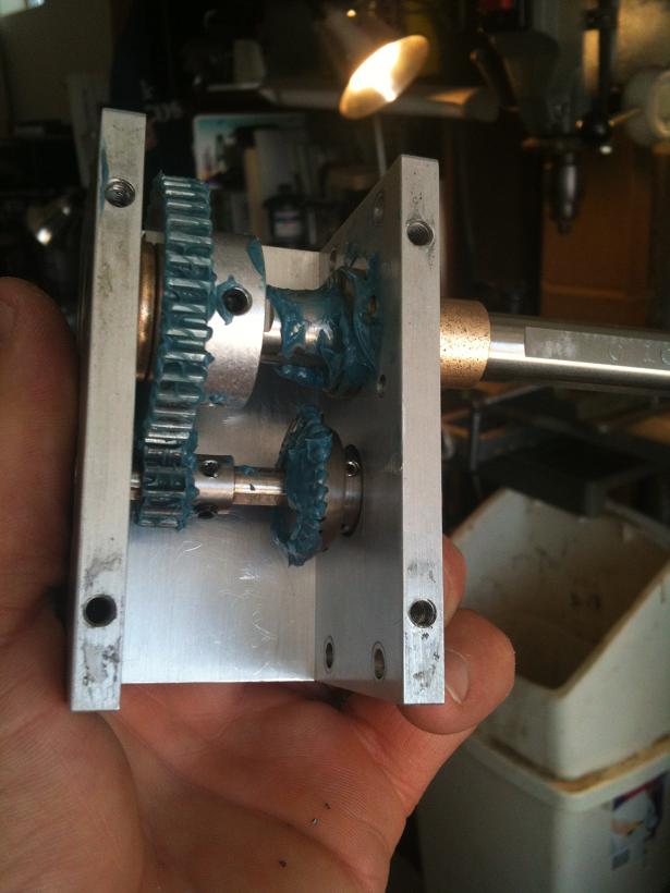
And, then the focus - once again - turned to the gearboxes.... Backlash was considerable and so after popping off the Alt gearbox cover it was noticed that the larger bevel gear would turn with the press of a button, but, the shaft wasn't moving until the set screw caught the edge of the shaft flat. Apparently the set screw had loosened. Tightening it did improve the view in the eyepiece but since when is it good practice to only put one set screw in gears?!?
After consulting with Gary at SC, rather than pay extra money on top of the $2800 already paid, plus other materials to rebuild nearly everything, the parts were brought home and put on the drill press to pin the gears - so they never shift again....
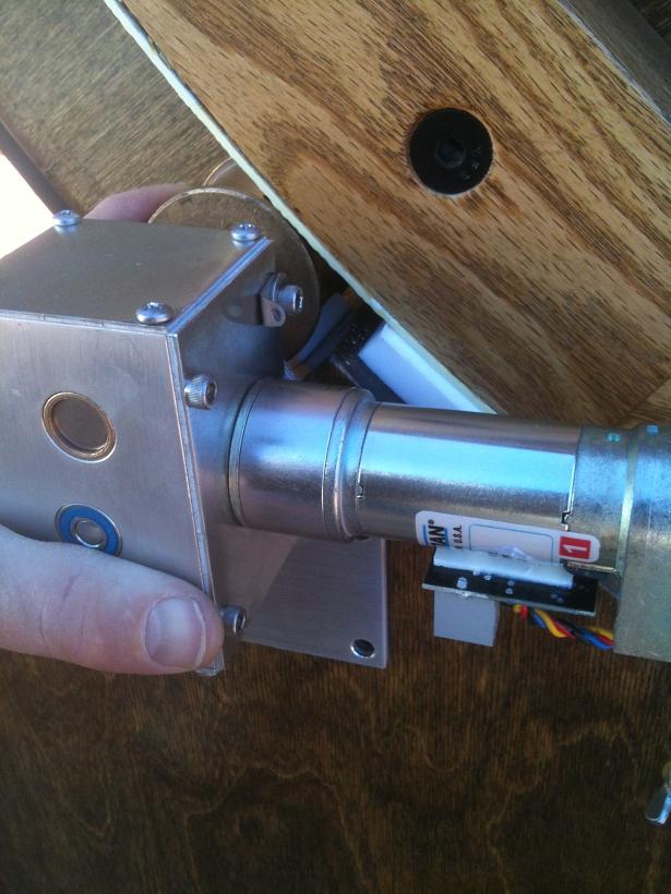
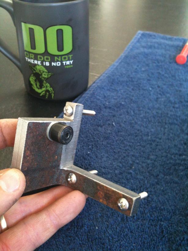
Another source of backlash is the knurl and spool on such long shafts that they flex as they try to move the scope and then the scope starts to move, and when you press the button for the opposite direction the flexure releases and then flexes in that opposite direction then the scope starts moving.... The backlash software value can't take care of that, so, brackets were created to hold the outer end of the spool using studded needle bearing guide and for the knurl a low profile bearing was used.
Here you can see the new bracket on the telescope. Since the Az pivot bolt is nearly tangent to the ground board like the knurl drive is, pinning those two together keeps the knurl in place and won't allow it to flex while then only allowed to rotate only on axis. The bracket is threaded and jam-nutted to the snug pivot bolt. The motor plate can pivot to bring in the knurl and the new bracket moves with the pivot bolt.
Here is the beginnings of a bracket for the Alt spool. When the spool rotates to raise or lower the scope the spool dips up or down as it tries to draw in the cable. While I created a steel mounting bracket to replace the aluminum one, when raising the scope the cable races out to the outer edge of the spool indicating the spool is no longer perpendicular to the Alt bearing so by pinning the outer spool end, it keeps the spool in place while allowed to rotate only on axis.
Here's the clip structure to keep the three winds in order, with the Alt cable extension installed when the stainless plate increased the circumference (rather than buy a new cable). The Alt axis is overextended more than allowed by computer control to take this picture.
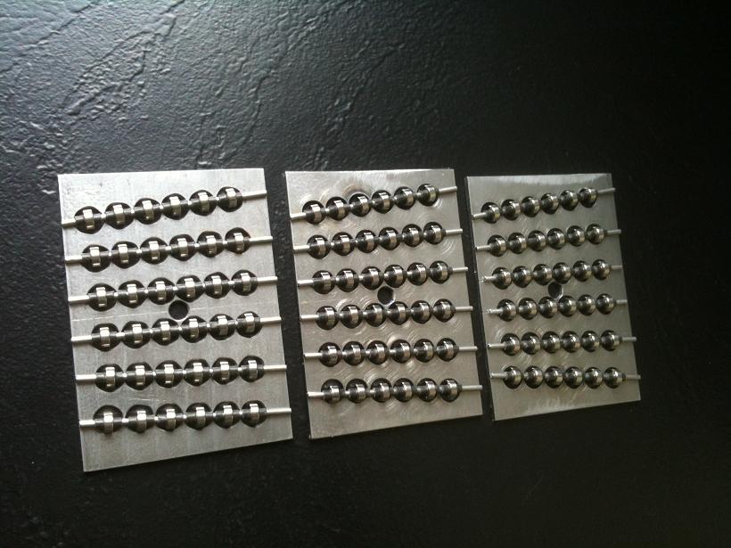
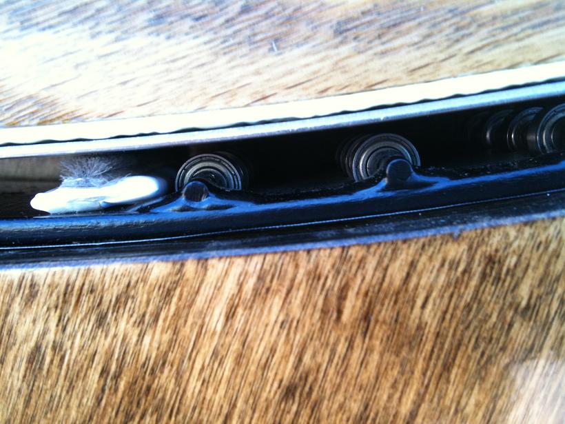
Here are the bearing plates made to support a 2500-pound telescope. The requirement was that they be drop-in replacements for the 3/8th inch Teflon plates.
Here's the layout of the bearing plates on the stainless plates, showing the area of the underside of the rock box which would actually be skinned in stainless but also the drawn rings for where screws could be placed and the travel zone for the bearings, plus the ServoCAT knurl hole and mounting hole.
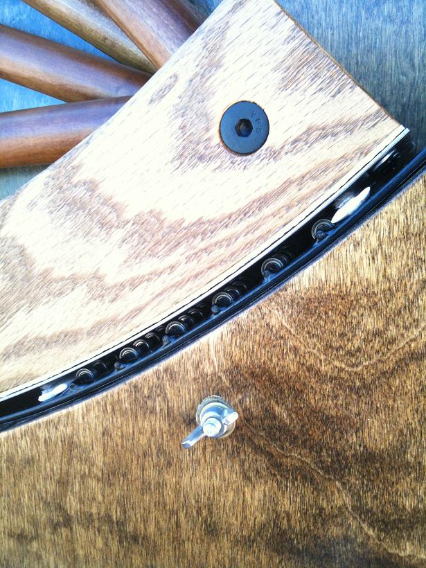
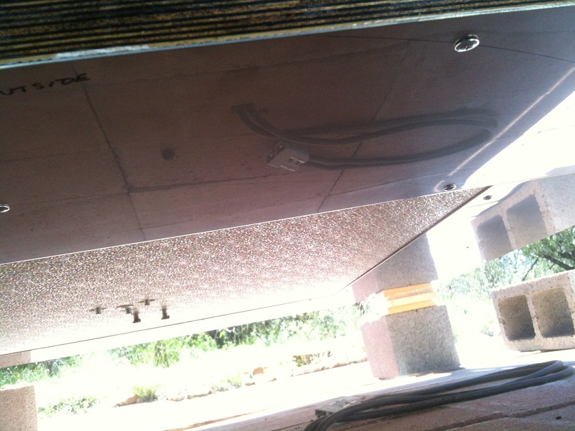
Here the scope is lifted up and ground board removed, showing the mirror surface of the stainless. Four rectangles are used and the bearing plates traverse the joint flawlessly as the shear cut deflects downward of each piece of the joint so there's no lip there.
Here's the ground board with the roller plates installed in place of the Teflon disks. It's now ready to place back under the telescope and set the scope down onto it.
Now, the Altitude at the spool only needs 5 pounds of force, and at the knurl for Azimuth only 2 pounds of force is needed. The backlash is in arc-seconds....